Saturn V - Apollo Flight Envelope |
 |
| The Flight path angle and the Velocity are two of the most significant performance parameters to monitor the flight trajectory of a launch vehicle. |
|
Selection of performance parameters to monitor the flight trajectory For proper flight control during the ascent phase, it is important to be able to detect deviations from the planned nominal flight trajectory in real time. For that purpose a strategic selection of the four most relevant performance parameters has been made. Deviations of these four parameters also reflect deviations from nominal values of the other six performance parameters mentioned in section "Performance characteristics".
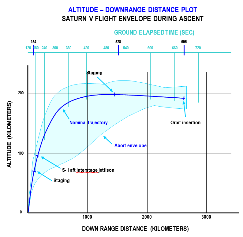
These charts contain plots representing the nominal flight trajectory and its envelope, reflecting the deviations which are allowed to have a (contingency) orbit attained. During the flight the real-time values of the performance parameters are plotted in these two charts on screens or plotboards. If the real-time plots cross the envelopes, an orbit cannot be attained and the crew safety is in danger; an abort procedure will therefore be initiated. The envelopes shown below are the result of simulation studies which were carried out in 1967 and 1968 by the TRW Systems Group by using the TRW Saturn Launch Simulating Program. In these studies carefully selected most critical malfunctions with regard to thrust control, engine failures and guidance have been simulated. All these malfunctions will result in a slowly developing deviation from the nominal flight trajectory. These simulations have shown to which extent these critical malfunctions are allowed till the ability to attain an orbit has been lost. A discussion about these simulation studies can be found on this page. |
|
|
Flight trajectory assessment: plotboard 1 This is the first plot of two used by Flight Dynamics officers to assess the ascent flight trajectory of the Saturn V launch vehicle. It enables them to react in time to an impending abort situation and inform the flight crew accordingly. |

|
|
Flight trajectory assessment: plotboard 2 The plot at the top is the second of two used by Flight Dynamics officers to assess the ascent flight trajectory of the Saturn V launch vehicle. It enables them to react in time to an impending abort situation and inform the flight crew accordingly. The plot starts at a point in which the inertial flight path angle is zero and the velocity is nonzero. That is because space has been chosen as the frame of reference; that implies that Earth's rotation is taken into account. So the launch vehicle already has a horizontal space-fixed velocity of about 410 meters per second due East when it is sitting on the launch pad in Florida. When the launch vehicle is ascending, the vertical component of the velocity is increasing, and therefore the inertial flight path angle is increasing. But at the same time the launch vehicle is starting to pitch over to gradually maneuver into an orbit in which it is aligned along the local horizon (flight path angle is zero). So the flight path angle increases at lift-off, will reach a maximum at which the vertical component of the velocity will reach a maximum, and will then taper off to zero when an orbit has been obtained.
The four launch abort modes
Abort mode IV (insertion into a contingency orbit)
Abort mode III If it is to land in the Atlantic Ocean to avoid a high-risk land landing on African soil, the reentry software of the Apollo Guidance Computer (AGC) needs flight data for proper descent trajectory control. These flight data basically contain data on the spacecraft's position, velocity, acceleration and the location of the selected landing area. The required flight data is acquired from the inertial navigation system, which is connected to the AGC. In the same short period of time, the flight crew has to initiate a propulsion maneuver with the Service Propulsion System to decrease the velocity, has to separate the command module from the service module and has to initiate the reentry procedure.
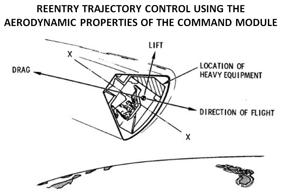
Controlling the lift vector by controlling the roll angle This mechanism enables the software by employing the Reaction Control System (RCS) to control the descent trajectory to have a controlled landing in a pre-selected landing area.
Abort mode II
Contingency orbit insertion using the S-IVB stage
Downrange distance, altitude and velocity |
| Acronyms | |
|---|---|
|
AGC Apollo Guidance Computer
COI Contingency Orbit Insertion RCS Reaction Control System |
|
References
|
Site Map |
References |
Change History
|
Comments and questions are welcome. All pictures and drawings contained on and through these pages are the author's, unless otherwise noted. No unauthorized reproduction without permission. |