The Mission Control Center (MCC)


Building 30: Mission Control Center (MCC)

Credit to NASA.
Figure 1
Mission Control Center (MCC)

The MCC building had three wings: on the left side the Operations Wing, on the right side the Mission Support Wing (or Administration Wing) and a Lobby Wing in the center. The Operations Wing had two Mission Operations Control Rooms (MOCRs) on the second and third floors, respectively. The elaborate systems for mission support, the Real Time Computer Complex (RTCC) and the Communication, Command And Telemetry Center (CCATS); were located on the first floor.


MCC floor plans
MCC MCC
Diagram based on ref.1, figures 1-2-1-1, 1-2-1-4 and 1-2-1-7.

Hotspots:
1. Purple area is linked to RTCC description
2. Brown area is linked to CCATS decription

Figure 2
MCC first floor
The elaborate systems for mission support, the Real Time Computer Complex (RTCC) and the Communication, Command And Telemetry Center (CCATS), were located on the first floor.
MOCR MOCR
Diagram based on ref.1, figures 1-2-1-2, 1-2-1-5 and 1-2-1-7.
Hotspots:
1. Orange area is linked to SSR description
2. Red area is linked to MOCR description
Figure 3
MCC second floor
In red is the Mission Operations Control Room no. 1 (MOCR-1). That is the room where the flight controllers were residing. That crew was supported by an elaborate staff sitting in separate rooms, the Staff Support Rooms (SSRs), across the corridor on the same floor.

MOCR-1 has been mainly used for training and simulation. However, the following missions have been controlled from MOCR-1: Apollo 5, Apollo 7, the Skylab missions and the Apollo-Soyuz Test Project.

MOCR MOCR MOCR
Diagram based on ref.1, figures 1-2-1-3, 1-2-1-6 and 1-2-1-7.
Hotspots:
1. Orange area is linked to SSR description
2. Red area is linked to MOCR description
3. Green area is linked to RCR description
Figure 4
MCC third floor
In red is the Mission Operations Control Room no. 2 (MOCR-2). That is the room where the flight controllers were residing. That crew was supported by an elaborate staff sitting in separate rooms, the Staff Support Rooms (SSRs), across the corridor on the same floor.

MOCR-2 was used as the primary room for flight control and mission management.
It has been used for the Gemini missions 4 to 12 and all the Apollo missions in which the Saturn V was used as the launch vehicle.
(The Gemini missions 1, 2 and 3 were controlled from the Mercury Control Center at Cape Canaveral Missile Test Annex, Florida.)

On the same floor the Recovery Control Room (RCR) was located. This room arrangement bears some resemblance to MOCR. The crew of the RCR was in command in the last phase of the mission when the command module was re-entering Earth's atmosphere and was on its way to its calculated landing area somewhere in the Pacific Ocean. There was a window between MOCR-2 and the RCR; it enabled the DOD officer, sitting at the top row in MOCR-2, to keep an eye on the activities in the RCR. DOD was responsible for the recovery activities.


Organization of Mission Control Center (MCC)
Seven Main Groups of Mission Control

Based on ref.1, figure 5-1
Figure 5
Seven Main Groups of Mission Control

The organization of Mission Control consisted of seven groups as shown above.
The first five groups were considered to reflect the five main areas of control:

  1. Mission Command and Control
  2. Mission Command and Control Support
  3. Flight Dynamics
  4. System Operations
  5. Public Affairs and Information Control

Mission Control Center Organizational Chart

Based on ref.1, figure 5-1
Figure 6
The Organization of Mission Control Center (MCC)

In this diagram the organization of the MCC is shown in more detail.


The main systems of the Mission Control Center
CCATS RTCC MOCR MOCR SSR SSR RCR MSTF FCTB
Diagram based on descriptions and functional block diagrams in ref.1, section III.
Hotspots:
1. RTCC part of diagram is linked to RTCC description
2. CCATS part of diagram is linked to CCATS decription
3. SSRs for training (green)
4. MOCR for training (green)
5. MOCR for mission support
6. RCR for mission support
7. SSRs for mission support

8. JSC MSTF, Mission Simulation and Training Facility
9. KSC FCTB, Flight Crew Training Building

Figure 7
Data flow and voice between the spacecraft and Mission Control

The Communication, Command and Telemetry System (CCATS) was the heart of a communication system between the spacecraft and the flight controllers. CCATS was connected to an elaborate worldwide network of tracking stations, stations to maintain data and voice communication with the spacecraft and communication relay satellites. CCATS had three UNIVAC 494 mainframe computers for data processing: one as the Mission Operational Computer (MOC), a second as a Dynamic Standby Computer (DSC) and a third UNIVAC 494 as a reserve available for other tasks.

The Real Time Computer Complex (RTCC) was used to transform data from CCATS into data suitable to display on the various console screens used by the flight controllers. The RTCC was also used to calculate and plot flight trajectories and to prepare data and commands to be uploaded to the spacecraft's on-board computer via CCATS. With five IBM 360 mainframes, the RTCC had more computer redundancy than CCATS with its three UNIVAC 494s.

In this diagram is shown how CCATS and RTCC could be configured in such a way that both centers can support an ongoing mission and support the training of flight controllers for the next mission at the same time. There were two Mission Operations Control Rooms (MOCRs) available to enable mission support and training simultaneously.

The UNIVAC 494s were used as communication processors and the IBM 360s as real-time data processors.

ASCATS
A system named ASCATS (Apollo Simulation Checkout And Training System) was used to simulate an Apollo mission.
The data generated by ASCATS to simulate data from the launch vehicle, spacecraft and remote sites were indistinguishable from real mission data. With ASCATS data could be generated to simulate all kinds of malfunctions to train the crew, prepare them for various eventualities and validate procedures. ASCATS could be configured in various ways for training the crew of the Mission Control Center, for training the astronauts and for training the crew at various remote sites. In a so-called integrated simulation, all groups were involved. ASCATS could be linked to a spacecraft trainer at JSC, building 5, or to a spacecraft trainer at KSC (Kennedy Space Center) in the FCTB (Flight Crew Training Building).

ASCATS was temporarily housed in building 422; as depicted in the diagram, it had one UNIVAC 494, one IBM 360-75 and peripheral equipment. The UNIVAC 494 was used as the Apollo Process Control Unit (APCU) and the IBM 360-75 as the Ground Support Simulation Computer (GSSC).
The GSSC was able to generate data to act as a simulator for remote sites, for the spacecraft trainer, for MCC and for all three entities at the same time in an integrated simulation. ASCAT was controlled from the Apollo Simulation Control Area (ASCA). From ASCA, faults could be inserted into the data streams to create simulated error conditions or simulated system malfunctions for training purposes.
ASCATS also contains a facility, Apollo Simulated Remote Site (ASRS), to train remote site personnel.

ASCATS was moved to the MCC in 1969. Its UNIVAC 494 and the IBM 360-75 computers were disposed of because one of the five computers of the RTCC and one of the three computers of the CCATS could be made available for training sessions.

GSFC
The Goddard Space Flight Center, in Greenbelt, Maryland, was the hub of the Manned Space Flight Network (MSFN), a worldwide network of tracking stations.


Diagram based on ref.1, figures 3-1 and 3-2.
Figure 8
Mission Control Center, Functional Block Diagram

In the diagram above, three major systems can be distinguished. A breakdown of these three systems is given below.

  1. The Communications, Command and Telemetry System (CCATS)
    1. Communications Facility Control Subsystem
    2. Voice Communications Subsystem
    3. Telemetry Subsystem
    4. Central Processor Subsystem
    5. Teletype and Fascimile Subsystem
    6. Pneumatic Tube Subsystem
  2. The Real Time Computer Complex (RTCC) System
    1. RealTime Computer Complex (RTCC)
    2. RTCC Control
    3. Auxiliary Data Processing Subsystem
  3. The Display/Control System
    1. Computer Display/Control Interface Subsystem
    2. Timing Subsystem
    3. Television Subsystem
    4. Group Displays Subsystem
Nearly all communications and exchange of data between MCC and the outside world went through the MCC Telephone Termination and Distribution Equipment.

The Television Subsystem and the Group Display Subsystem were used to present all the mission-related information to the mission controllers in MOCR, the staff in the SSRs and the RCR.

CCATS and RTCC
The three systems, CCATS, RTCC and the Display/Control System, are depicted in a functional block diagram shown in figure 6.
The diagram shows the mutual relationships between the three systems. CCATS had a prominent role in managing and processing communication and data traffic. The RTCC provided support to the CCATS by processing data.
The RTCC, with its five IBM 360/75J mainframes, had much computer power and was considered the top of the high-end computers in the late sixties / early seventies. The RTCC was also used to do all kinds of analysis on data for the mission controllers with regard to spacecraft systems, tracking and trajectory control. Programs were frequently running to provide data for the required spacecraft attitude, thrust vectors, burn times and time to enable the spacecraft to change its trajectory to correct its trajectory or change it into a contingency trajectory in case of emergencies. Several programs could be running on a single mainframe virtually simultaneously thanks to its job management capability to use its CPU efficiently. It enabled the mission controllers to maintain optimal situational awareness and anticipate various events in this dynamic mission environment.

Display/Control System
The funny blue L-shaped and U-shaped bars in the block diagram above depict the supporting role of the Display/Control System in providing and presenting data to the controllers in the RCR, the SSRs, the MOCRs, the RTCC Control Room and the CCATS Command Room.
Some of the MOCR controllers could also submit computer requests via the Computer Display/Control Interface Subsystem to the RTCC and submit command initiation requests to CCATS. These command initiation requests were basically instructions for a remote site computer and were formatted and sent by CCATS through a network of remote site computers. The RTCC, CCATS and this network of remote site computers were the backbone of the Command Subsystem. This system enabled the mission controllers to control the spacecraft.
The U-shaped bars illustrate that the RTCC Control Room was part of the RTCC Computer Control Subsystem and was supported by the Display/Control System. Also the control equipment of the CCATS subsystems was supported by the Display/Control System.


A transcendent system: the Command Subsystem
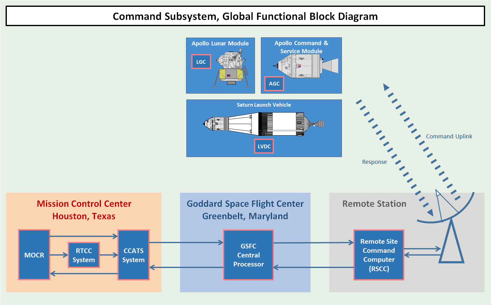
Diagram derived from ref.1, figure 3-2-3.
Figure 9
The Command Subsystem

The Command Subsystem is not depicted explicitly in Figure 8. This subsystem was used for preparing and processing command data and transmitting them to the spacecraft or launch vehicle. This command subsystem refers to computer systems and communications systems of the MCC and the Manned Space Flight Network (MSFN). It is in that sense more referring to a network of systems than to a particular system.
The Command Subsystem was also known as the Universal Command System or the Apollo Digital Command System (DCS).

The RTCC was used to prepare the command data, which could be real-time commands (RTCs), program updates or data to be uploaded to the computers of the Launch Vehicle Digital Computer (LVDC) and of the Apollo spacecrafts (AGC and LGC).

The RTCs were commands which were executed immediately and were used to control the systems of the Saturn V launch vehicle or systems of the Apollo spacecrafts and to control the onboard computers. For example, if during the S-II stage boost phase a failure would occur which would require the jettison of the S-II stage and the ignition of the S-IVB stage, the current guidance program running on the LVDC would need to be aborted and an alternative guidance program would need to be initiated by an RTC.

The program updates and the data were used to update the spacecraft's guidance computer; it basically enabled the mission controllers to do maintenance on the guidance computer remotely.

For a more elaborate description of the Command Subsystem, see the page about The Command Subsystem.


Acronyms
AGC Apollo Guidance Computer
APCU Apollo Process Control Unit
ASCA Apollo Simulation Control Area
ASCATS Apollo Simulation Checkout And Training System
ASRS Apollo Simulated Remote Site
CCATS Communication Command And Telemetry System
DCS Digital Command System
DSC Dynamic Standby Computer
DSKY Display and keyboard
FCTB Flight Crew Training Building
FIDO Flight Dynamics Officer
GSSC Ground Support Simulation Computer
JSC Johnson Space Center (Houston, Texas)
KSC Kennedy Space Center (Florida)
LGC Lunar Module Guidance Computer
LVDC Launch Vehicle Digital Computer
MCC Mission Control Center
MOC Mission Opereational Computer
MOCR Mission Operations Control Room
MSC Manned Spacecraft Center
MSFN Manned Space Flight Network
MSTF Mission Simulation and Training Facility
RCR Recovery Control Room
RETRO Retrofire Officer
RTCC Real-Time Computer Complex
SSR Staff Support Room
Note: MSC has been renamed to JSC in 1973.

References
  1. Familiarization Manual
    Mission Control Center Houston
    PHO-FAM001, 30 June 1965
    by Western Development Laboratories, Houston Operations

  2. AS-508; MCC / MSFN; Mission Configuration / System Description
    March 1970
    by the Manned Spacecraft Center, Flight Support Division

  3. Mission Operational Configuration
    Mission J1, AS-510 / SC122 / LM10, Apollo 15
    PHO - TR155, 15 April 1971
    Manned Spacecraft Center, Houston


Site Map |  References |  Change History

Copyright 2020 by Sander Panhuyzen
Comments and questions welcome. All pictures and drawings contained on these pages are the author's, unless otherwise noted. No unauthorized reproduction without permission.