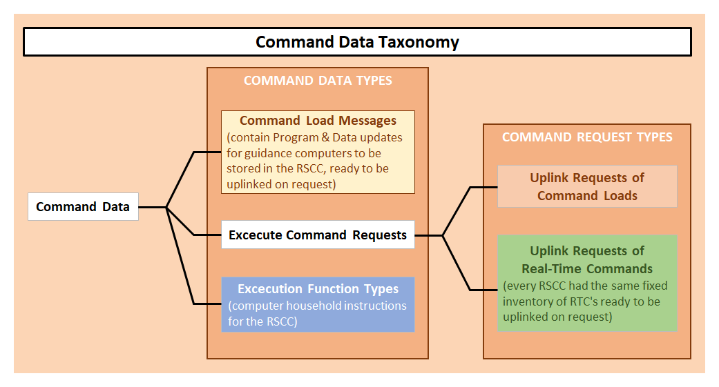
The Command Subsystem


Preface
The purpose of the Command Subsystem was to enable the Mission Control Center (MCC) to control and command the Apollo spacecrafts and the Saturn launch vehicle. Command data could be uplinked to the spacecraft from a network of remote site stations at the request of the MCC. For that purpose the command data were kept in storage at the remote site stations, ready to be uplinked. The Goddard Space Flight Center was the hub of this elaborate network of stations through which the command requests were sent.

On this page are discussed:

  1. The geographic network of the Command Subsystem
  2. The Command Subsystem's principle of operation, which includes the type of commands which could be sent
  3. Functional overview of the Command Subsystem
  4. Overview of the command loads and the real-time commands of the Apollo 11 mission, which includes some explanation about their various purposes.
  5. The command initiation procedures and the employed command panels of the control consoles
Note to the reader
Much of the information about the operational procedures of the Command Subsystem, including how the command panels on the control consoles were used, has been lost. With a lot of guessing and iteration, I have tried to reconstruct the procedures, but this reconstruction is still full of gaps. In the attachment of this page I have started a discussion about the command panels and the procedures in the hope that it might invite knowledgeable people to help fill in the gaps or put me on the right track.

To me, the Command Subsystem, which enabled the mission controllers to control the spacecraft remotely, is one of the most intriguing parts of the Apollo mission control.


1.Command Network for the Apollo 11 Mission

Drawing based on ref.2 figure 2.
Ship locations based on ref.5 page 71, tabel 5.
Figure 1
Geographical locations of the remote stations to uplink commands to the Apollo spacecrafts.

From the Mission Control Center (MCC) commands could be sent to the spacecrafts via a network of communication stations. The Goddard Space Flight Center (GSFC) was the hub of this network.

The network was actually comprised of the Manned Space Flight Network (MSFN) and the Deep Space Network (DSN). The MSFN consisted of a network of eleven land-based stations and four ship-based stations. The DSN consisted of three land-based stations; each station had two antenna dishes of 85 ft and 210 ft diameter, respectively. The maximum antenna diameter of an MSFN station was 29 ft. The MSFN could be used for distances up to 60 000 km and was developed to support Earth orbital missions. To conduct moon missions, distances up to 400 000 km had to be covered. So when the distances to the Apollo spacecrafts exceeded 60 000 km, tracking and communication were provided by the DSN stations MAD, HSK and GDS.

The locations of the ship-based stations were determined by the mission-specific tracking requirements in the four critical mission phases near Earth. The purpose of station VAN was to determine trajectory parameters with the required accuracy at the moment of Earth Orbit Injection at the end of the launch phase. The purpose of the stations MER and RED was to determine the state vector (position, velocity and acceleration) of the spacecraft during and just after Trans Lunar Injection. The mission of station HUN was to determine state vectors in the reentry phase.


Equipment matrix based on ref.11, figure 9-9.
Selection of stations based on ref.5 page 73, tabel 6.
Figure 2
The equipment of the various MSFN sites.

The hub of the MSFN and the Mission Control Center are marked in red.
The three stations of the Deep Space Network with their 85-foot dish antenna are marked in red lettering.
All stations, except for station HUN, are equipped with Unified S-band (USB) equipment. It was a relatively new technology to use a single carrier frequency in the 2-4 GHz band for voice, TV and data communication and for tracking (range and velocity). The range of the transmit band was between 2.090 and 2.120 GHz and the receive band between 2.270 and 2.300 GHz. To provide communication and tracking on a single carrier signal with a set of subcarrier signals, a bandwidth of 4 MHz was used. Therefore, by using two carrier signals 5 MHz apart, tracking and communications could be provided for two spacecrafts simultaneously.


2.Command chain: MCC - GSFC - Remote Site - Spacecraft


Diagram based on descriptions in ref.1.

Figure 3
Principle Block diagram.

In this diagram is shown that:

  1. The command chain consisted of four components: the MCC, GSFC, the remote site and the spacecraft.
  2. that the MCC could send three types of command data and that, of the command data type, the execute command request was subdivided into two types:
    1. requests to uplink command loads
    2. requests to uplink real-time command (RTCs)
The execution function types allowed an operator at the MCC to operate the RSCC and its peripheral equipment, such as tape drives, remotely.

3.Functional overview of the command subsystem

Diagram based on ref.1, section 3-2-3 and figure 3-2-3.
Figure 4
Functional block diagram of the command subsystem.

In this diagram is indicated which controllers had command panels on their consoles to initiate uplinks of command loads or real-time commands (RTCs) to the spacecraft:

  • MOCR controllers: BOOSTER, GUIDO, CONTROL and INCO
  • CCATS controllers: Command Load Controller and Computer Command Controller
  • CCATS controllers in a supporting role: Real-Time Controller and Telemetry Instrumentation Controller
    Their role was related to the formatting and routing of the command data messages.
  • RTCC controllers: RTCC Network & Command Process Controller ?
Personal reminder 1
The grey blocks refer to the supposed option to conduct end-user tests if command loads will have an impact on the way astronauts have to interact with AGC or LGC. I need to check on that. The command panels I am referring to seem to be unnecessary for requesting to uplink command loads or RTCs. And conducting end-user tests to check on the usability when a command load affects the interaction between the crew and guidance looks essential to me. And since the flight controller was responsible for final acceptance of a created command load, it would make sense to me that this officer had the means to perform the tests.

Personal reminder 2
I need to check whether and how the RTCC Network & Command Process Controller could initiate uplinks. The primary responsibility was to generate command loads on request of a MOCR controller. The console of this RTCC controller was equipped with panels, which seems to suggest that uplinks could be initiated.


Diagram based on information from ref.2, 11 and 12
Figure 5
Voice loop for requesting the generation of command loads

In this diagram is shown which MOCR controllers were involved in generating command loads and which controllers were required to request uplinks of command loads and RTCs.

Load generation requests
According to ref.11 on page 9-6 the controllers BOOSTER, FIDO, GUIDO and RETRO were required to request the generation of command loads. According to the voice loop configuration as depicted above, the voice loops "RTCC DYN", "REENTRY SUPPORT" and "RTCC CMD NET" were used by these four MOCR controllers to request a so-called command load generation. These three voice loops were monitored by the RTCC Computer Command Controller, who was responsible for generating the command loads.
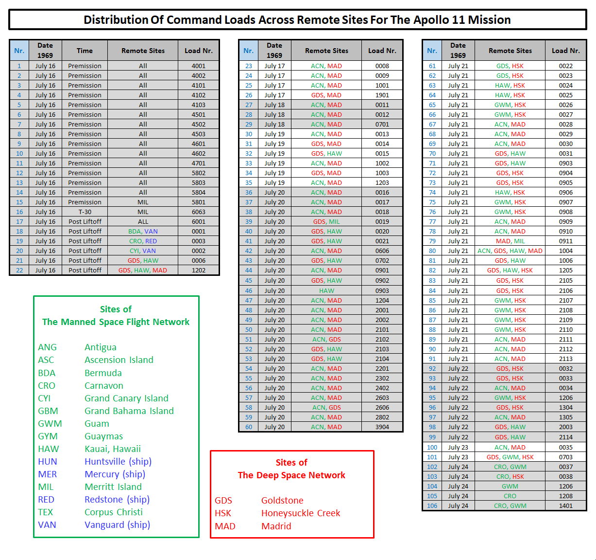
When they have gone through the generation process, the command loads were transferred to various remote sites, if not to all, on request of the MOCR controller.

Uplink requests
The consoles of the controllers INCO, CONTROL, BOOSTER and GUIDO were equipped with command panels to send requests via CCATS to a remote site to uplink a command load or an RTC to the spacecraft.
It is remarkable, however, that the controllers FIDO and RETRO were required to request a command load generation but that their consoles were not equipped with command panels to request an uplink.
Note 1
I assume that FIDO and RETRO had several options to have an uplink requested:

  1. Asking their colleague controllers GUIDO and BOOSTER to request an uplink using their command panels.
  2. Based on ref.2 figure 1, the CCATS Command Controller (CCC) could dispatch an uplink request on behalf of a MOCR Controller.
  3. Asking the RTCC Computer Command Controller to request an uplink. I assume the RTCC CCC was using the teletype to issue the request via CCATS. I also assume that the RTCC CCC could use voice loop "RTCC CMD NET" to pass the request on to the CCC.
Note 2
The EECOM links of the voice loops have been derived from ref.13 in which a detailed rendering is shown of the keyset unit of the EECOM console. A keyset unit enabled a MOCR controller to monitor voice loops and participate in the conferences on those loops. The EECOM voice loop links as shown in the drawing are based on the key inscriptions of the keyset unit. It would make sense to me that the other system engineers, GNC, TELMU and CONTROL, which had similar responsibilities as EECOM, would have access to the same voice loops. So I have drawn the links as dotted lines to denote that these links are assumed.

Note 3
The consoles of the system engineers / MOCR controllers EECOM, GNC, and TELMU were not equipped with command panels to request uploads of command loads or real-time commands (RTCs). The console of their colleague system engineer CONTROL was, however, equipped with command panels. Since it seems obvious to me that the system engineers needed to control spacecraft systems remotely, I assume they requested uploads of RTCs via CONTROL.

Note 4
Another option for requesting uplinks would have been asking support from the CCATS controllers. I assume that the system engineers were using voice loop "RTC" to issue an upload request. The name "RTC" refers to the fact that the CCATS Real-Time Controller (RTC) was central in this voice loop. The RTC established the command data channel by selecting the console of the applicant and the remote station from which the RTC must be uplinked. I therefore assume that the voice loop "RTC" was monitored by the CCC to be able to act promptly and request an uplink on behalf of the MOCR system engineer. I also assume that this voice loop was monitored by the CCATS Command Load Controller and the RTCC CCC.


4.Command Loads and Real Time Command (RTCs)
There were two types of command data which could be uploaded to the spacecraft or the launch vehicle:
  1. command loads
    to control the guidance computers LVDC, AGC and LGC.
  2. real-time commands (RTCs)
    to control systems and subsystems of the launch vehicle and the spacecrafts from the ground

Based on ref.4, section 3.3.5


Based on ref.4, section 3.3.5, tabel III.

Figure 6
Command Loads.

106 Different command loads have been distributed; 16 of them were distributed prior to lift-off, and 90 load commands have been distributed during the mission. The content of the load commands depended on the mission circumstances, such as trajectory parameters, for example. So to create a command load the most recent data had to be fed into this creation process. In the bottom table, it can be seen that 58 load commands have been uplinked.

Note 1
These figures might illustrate that it was probably policy to have command loads created in advance to anticipate possible requests during the validity periods of the command loads.
However, command loads could also be created on the spot to have them uplinked as soon as possible. In the list above a distinction between these in situ command loads and the normal command loads has not been made, leaving us clueless about to what extent MCC still had to react to unforeseen events.

Note 2
I have also not been able to find any substantive information about the command loads and the rationale behind the number methodology. It would be interesting to know what kind of command loads were uplinked or were kept ready in the various mission phases, their purpose and for which guidance computers they were intended. I assume that all the pre-mission command loads were intended for the LVDC, and probably most of them were intended for contingencies like the various abort modes and forced staging. The "T-30" command load might have been depending on the latest flight parameters (flight azimuth in relation to expected time of launch, ascent profile optimization in relation to wind conditions ?)


Based on ref.4, section 3.3.5, tabel II.

Figure 7
Real Time Commands (RTC).

In this overview is shown how many Real-Time Commands (RTCs) were uplinked. By far the most RTCs were uplinked via the three stations of the Deep Space Network (HSK, GDS and MAD).

The global timeline of the Apollo mission provides some context in which the RTCs have been uplinked over the course of nine days.

Personal note
The system configuration of the Saturn Launch vehicle and the spacecrafts could differ per mission. Therefore the RTC inventory might differ per mission. These RTCs were used to flip a particular valve or switch on/off a system component, such as an onboard tape recorder, for example. So the RTC inventory was set when the system configuration was set. The RSCC could be provided with all the RTCs well in advance.
However, I have not been able to find any listing of RTCs containing information about the RTC numbering and their purpose.

Personal reminder
In the overview 17 RTCs seemed to have been uplinked from HAW on 19 July 1969. That surprises me. First, at that date the S-IVB stage, the CSM and the LM were all in the vicinity of the Moon, well beyond the range of the HAW station, so I thought. I need to check on its range. And second, the three DSN stations MAD, HSK and GDS together could provide 100% coverage with regard to communication and tracking for space vehicles beyond 30 000 km from Earth, rendering all other stations redundant.


5.Command Panels for BOOSTER, GUIDO, INCO and CONTROL

Drawings based on information from ref.2
Figure 8
Command Panels for BOOSTER, GUIDO, INCO and CONTROL

This pictorial description of how an uplink of a command load was requested is based on descriptions in ref. 1, 4, 11, 12 and 14.

The command panels.
Panel 1: the Control Mode Module (CMM)
Panel 2: the Digital Select Matrix (DSM)
Panel 3: the Digital Readout Module (DRM)

The RTC PBI panels, which enabled the flight controller to uplink a specific RTC with the push of a button, are not depicted in this figure.

In Figure 4 it is shown that the command panels were connected to an encoder to convert a key entry into a digital code.


Acronyms
AGC Apollo Guidance Computer
AVP Address Verification Pulse
CAP Command Analysis Pattern
CCATS Communication Command And Telemetry System
CCC CCATS Command Controller
CIM Computer Input Multiplexer
CMM Control Mode Module
CRP Computer Reset Pulse
DSKY Display & Keyboard
DRM Digital Readout Module
DSM Digital Select Matrix
DSN Deep Space Network
GOSS Ground Operational Support System
GSFC Goddard Space Flight Center
GUIDO Guidance Officer
INCO Instrumentation and Communication Officer
JSC Johnson Space Center (Houston, Texas)
KSC Kennedy Space Center (Florida)
LGC Lunar Module Guidance Computer
LVDC Launch Vehicle Digital Computer
MAP Message Acceptance Pulse
MCC Mission Control Center
MOCR Mission Operations Control Room
MSC Manned Spacecraft Center (Houston, Texas)
MSFN Manned Space Flight Network
PBI Push Button Indicator
PTT Pneumatic Tube Transport
RETRO Retrofire Officer
RSCC Remote Site Command Computer
RTC Real Time Command
RTCC Real-Time Computer Complex
RTCC CCC RTCC Computer Command Controller
TLM Telemetry
UHF Ultra High Frequency
USB Unified S-Band
Note: MSC has been renamed to JSC in 1973.

References
  1. Familiarization Manual
    Mission Control Center Houston
    PHO-FAM001, 30 June 1965
    by Western Development Laboratories, Houston Operations

  2. AS-508; MCC / MSFN; Mission Configuration / System Description
    March 1970
    by the Manned Spacecraft Center, Flight Support Division

  3. Mission Operational Configuration
    Mission J1, AS-510 / SC122 / LM10, Apollo 15
    PHO - TR155, 15 April 1971
    Manned Spacecraft Center, Houston

  4. Network Controller's Mission Report Apollo 11
    Prepared by Flight Support Division
    Manned Spacecraft Center, Houston
    15 August 1969

  5. Mission Operation Report
    Apollo 11 (AS-506) Mission
    Report No. M-932-69-11, 24 June 1969
    Prepared by Apollo Program Office
    Office of Manned Space Flight

  6. Apollo C-Band Radar Tracking Capability
    Apollo 11 (AS-506) Mission
    by P.R. Schmid
    Goddard Space Flight Center, Greenbelt, Maryland
    15 September 1967

  7. Ground Tracking of The Apollo
    Apollo 11 (AS-506) Mission
    by Friedrich O. Vonbun
    Goddard Space Flight Center, Greenbelt, Maryland
    1 January 1965

  8. Apollo Digital Command System
    by C.B. Cox
    Goddard Space Flight Center, Greenbelt, Maryland
    Proceedings of the Apollo Unified S-Band Technical Conference
    July 14-15, 1965

  9. Apollo Remote Site Display System
    by G.N. Georgeadis
    Goddard Space Flight Center, Greenbelt, Maryland
    Proceedings of the Apollo Unified S-Band Technical Conference
    July 14-15, 1965

  10. Command and Communication System
    by B. Reed
    Marshall Space Flight Center, Huntsville, Alabama
    Proceedings of the Apollo Unified S-Band Technical Conference
    July 14-15, 1965

  11. Saturn V Flight Manual SA-506 (Apollo 11)
    George C. Marshall Space Flight Center
    MSFC-MAN-506, 25 February 1969
    page 9-5 and 9-6

  12. Project Apollo 500 RTCC Operations Support Plan For Mission G
    MSC Internal Note No. 69-FS-2
    Flight Support Division, Flight Software Branch
    Manned Spacecraft Center, Houston, April 1969

  13. Apollo 13 mission, EECOM console layout
    https://history.nasa.gov/afj/ap13fj/pdf-hr/a13-eecom-console.pdf
    Prepared by Andy Anderson
    From the Apollo 13 Mission Documents section of

    The Apollo 13 Flight Journal
    by David Woods, Johannes Kemppanen, Alexander Turhanov and Lennox J. Waugh
    NASA History Division

  14. Universal CSM Console Handbook
    S/C 106 and subsequent vehicles
    Section D5
    Flight Control Division
    Manned Spacecraft Center, Houston, May 1969


Site Map |  References |  Change History

Copyright 2023 by Sander Panhuyzen
Comments and questions welcome. All pictures and drawings contained on these pages are the author's, unless otherwise noted. No unauthorized reproduction without permission.