User procedures for the Command Subsystem


Preface
The Command Subsystem was also known as the Universal Command System or the Apollo Digital Command System (DCS).
This system enabled the Mission Control Center to command spacecrafts by sending commands and data to their guidance computers.

On this page the user procedures for commanding spacecrafts are discussed.
The message sequence diagrams in section 1 are a good representation of the procedural interplay between MOCR, RTCC, CCATS, the Goddard Space Flight Center, the remote tracking station and the spacecraft.
The consoles of the various controllers were equipped with control panels to use the Command Subsystem; these panels are all depicted on this page. However, an accurate description of how these panels were actually used is still lacking.


Content
In section 1, Message Sequence Diagrams are shown which depict the procedures for Command Load provisioning, for uplinking Command Loads and for uplinking Real-Time Commands.

In the sections 2 up to and including 9, the arrangements are shown of the command modules/panels and the real-time command PBI modules/panels of the consoles of:

  1.       BOOSTER
  2.       GUIDO
  3.       INCO
  4.       CONTROL
  5.       the RTCC Computer Command Controller (RTCC CCC)
  6.       the CCATS Command Load Controller and the CCATS Real Time Controller
  7.       the CCATS Command Controller (CCC)
  8.       the CCATS Telemetry Instrumentation Controller
In section 10 is shown the first iteration of a pictorial description of the procedures to uplink a command load or a real-time command. This section is currently under revision because it contains too many unknowns and raises too many questions.


1.Message Sequence Diagrams

Drawing based on descriptions in ref.1 section 3.2.3 and ref.9 section 8
Text

Drawing based on descriptions in ref.1 section 3.2.3 and ref.9 section 8
Text

Drawing based on descriptions in ref.1 section 3.2.3 and ref.9 section 8
Text

2.MOCR:  Console of the Saturn V booster stages system engineers  (BOOSTER)
The command panels of BOOSTER were used to operate the subsystems of the various stages of the launch vehicle. The commands were sent to the LDVC (Launch Vehicle Digital Computer), which was residing in the Instrument Unit on top of the S-IVB stage. The LVDC was part of the navigation and guidance system of the launch vehicle but also acted as a data and command hub of the various subsystems.

BOOSTER could send RTCs by using the RTC PBI panel or the DSM panel by submitting a numeric RTC ID.

Note
I conjecture that BOOSTER had the option to uplink command loads to update the software of the LDVC. These updates were very likely related to programmed sequences of operations of the subsystems. The LVDC contained a program for sequencing to facilitate proper stage separation, stage conditioning, rocket engine ignition and rocket engine shutdown. A network of all kinds of sensors throughout the launch vehicle acted as a feedback loop to enable the LVDC to take circumstances and performance factors into account when it went through a sequence.
It is conceivable that BOOSTER had the option to change this sequencing of operations and how it should respond to sensory input if, for some reason, the mission needed to be deviated from the nominal mission during the launch phase, the Earth orbital phase and the phase which involved the S-IVB stage. These updates from BOOSTER were not related to navigation and guidance because that was the responsibility of GUIDO.
I am looking for information on how BOOSTER was using the command panels and about the various commanding options which were available to BOOSTER.

3.MOCR:  Console of the Guidance Controller  (GUIDO)
The Data Entry Module (DEM)
Besides sending command loads and RTCs to the spacecraft, GUIDO also had the option to operate the spacecraft's guidance computer (AGC) via the DSKY, the user interface, remotely. The DEM (Data Entry Module) panel resembles the DSKY, which was the user interface of the Apollo guidance computer.
The display format "CSM DSKY AND STATE BUFFER MONITOR" represented the displays of the AGC's DSKY and enabled GUIDO to verify the entries.
Every keystroke on the DEM resulted in an Execute Command Request from MOCR to the AGC and a consecutive response from the AGC to MOCR.
Since there was no display format "LM DSKY AND STATE BUFFER MONITOR", I assume that this level of control over the guidance computer only applied to the AGC, the guidance computer of the Apollo CSM. And not to the LGC, the Lunar Module guidance computer.

4.MOCR:  Instrumentation & Communication Controller  (INCO)
INCO shared console 4 with the Operations & Procedures Controller (O&P). However, the task of controller O&P did not concern operating the command panels.

INCO mainly used RTCs for commanding the spacecraft, not for command loads, which were used for navigation and guidance. Navigation and guidance were not the concern of INCO. INCO used RTCs to operate the spacecraft's subsystem. Besides the RTC PBI panels to uplink the RTCs, INCO also used the DSM panel to uplink RTCs which were not available through the RTC PBI panels.

Panel 24, RTA Remote Control
I don't have a description about how this RTA remote control module was used.
RTA stands for Relative Time Accumulator(s).
It seems that they can be considered as clocks of which their T-minus-0 could be set at a time of choice on the mission timeline.
Above the large group displays in MOCR there were time displays located.
Various phases were distinguished in an Apollo mission, each with its own time base or T-minus-0. The relative time accumulators were parts of the timing subsystem to display the relative countdown time / elapsed time of a particular event or mission phase, taking the time base into account. Panel 24 had 7 PBIs with which an RTA could be instructed remotely to display the relative countdown time / elapsed time of 7 events, probably simultaneously. I suppose that unplanned events like a trajectory deviation burn could be inserted into the RTA scheduling.
But I am not sure. It could be that the RTA remote control unit was used during simulations only, to set the time for lift-off, for example.

5.MOCR:  Console of the Lunar Module GNC Systems Controller  (CONTROL)
Text

6.RTCC:  Console of the RTCC Command Controller
The RTCC Command Controller makes the Command Load on request of the MOCR Flight Controllers RETRO or GUIDO.

7.CCATS:  Console of the CCATS Command Load Controller and the CCATS Real Time Controller
The CCATS Command Load Controller (CCATS CLC) uploads a Command Load on request of the RTCC Command Controller to the Remote Site Command Computer (RSCC).

The CCATS CLC also managed the inventories of the function types, the command loads and the real-time commands.
The function types were instructions for the remote site computer.

The CCATS Real Time Controller (CCATS RTC) requests a Remote Site to uplink a particular Command Load from a selected remote station to the spacecraft at the request of a Flight Controller. A 4-digit Load Nr. refers to a specific Command Load to be uplinked to the spacecraft.

8.CCATS:  Console of the CCATS Command Controller
The Data Entry Module (DEM)
Besides sending command loads and RTCs to the spacecraft, the CCATS Command Controller also had the option to operate the spacecraft's guidance computer (AGC) via the DSKY, the user interface, remotely. The DEM (Data Entry Module) panel resembles the DSKY, which was the user interface of the Apollo guidance computer.
The display format "CSM DSKY AND STATE BUFFER MONITOR" represented the displays of the AGC's DSKY and enabled GUIDO to verify the entries.
Every keystroke on the DEM resulted in an Execute Command Request from MOCR to the AGC and a consecutive response from the AGC to MOCR.
Since there was no display format "LM DSKY AND STATE BUFFER MONITOR", I assume that this level of control over the guidance computer only applied to the AGC, the guidance computer of the Apollo CSM. And not to the LGC, the Lunar Module guidance computer.

9.CCATS:  Console of the CCATS Telemetry Instrumentation Controller
Text

10.Command Panels
Text

Acronyms
AGC Apollo Guidance Computer
AVP Address Verification Pulse
CAP Command Analysis Pattern
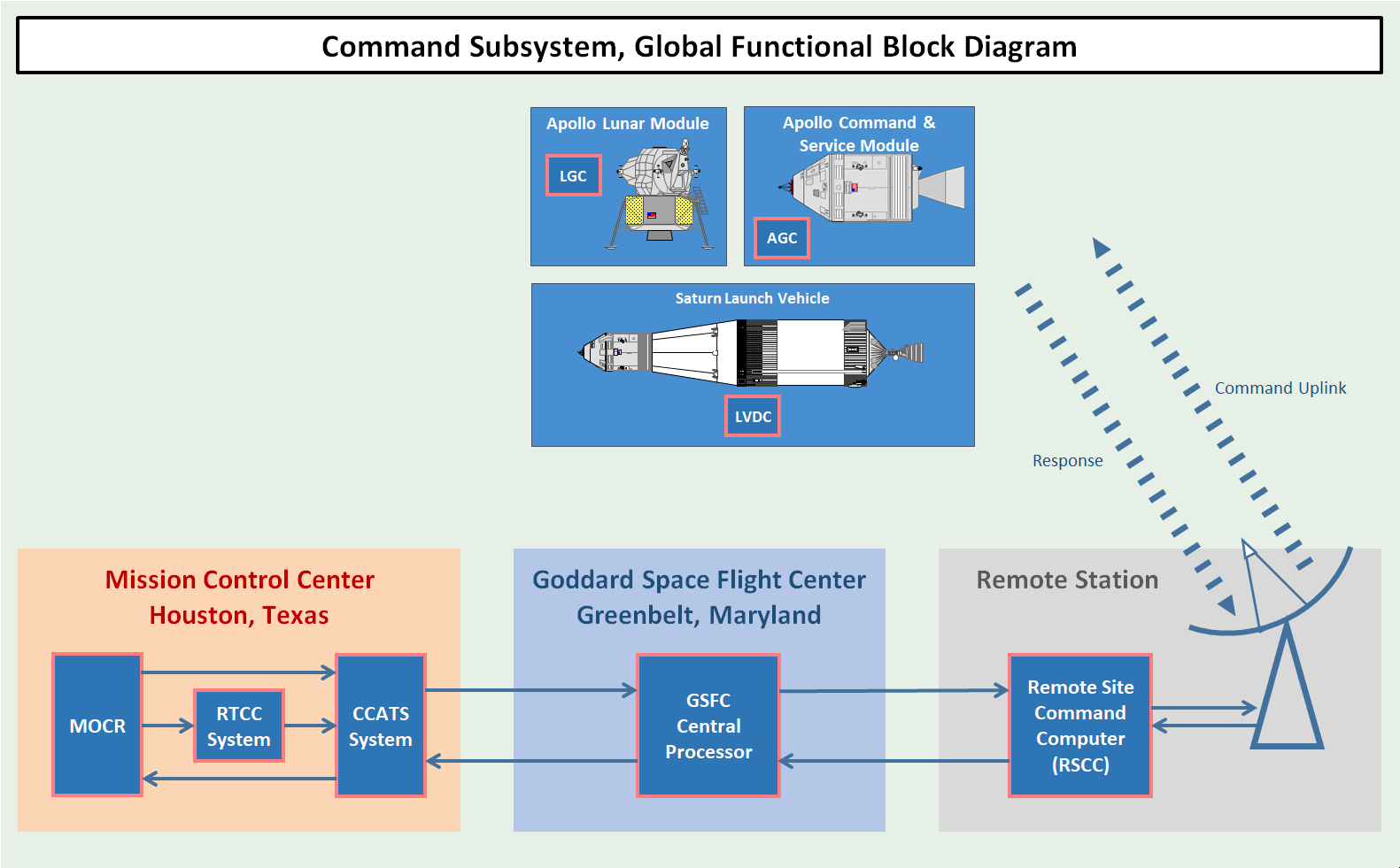
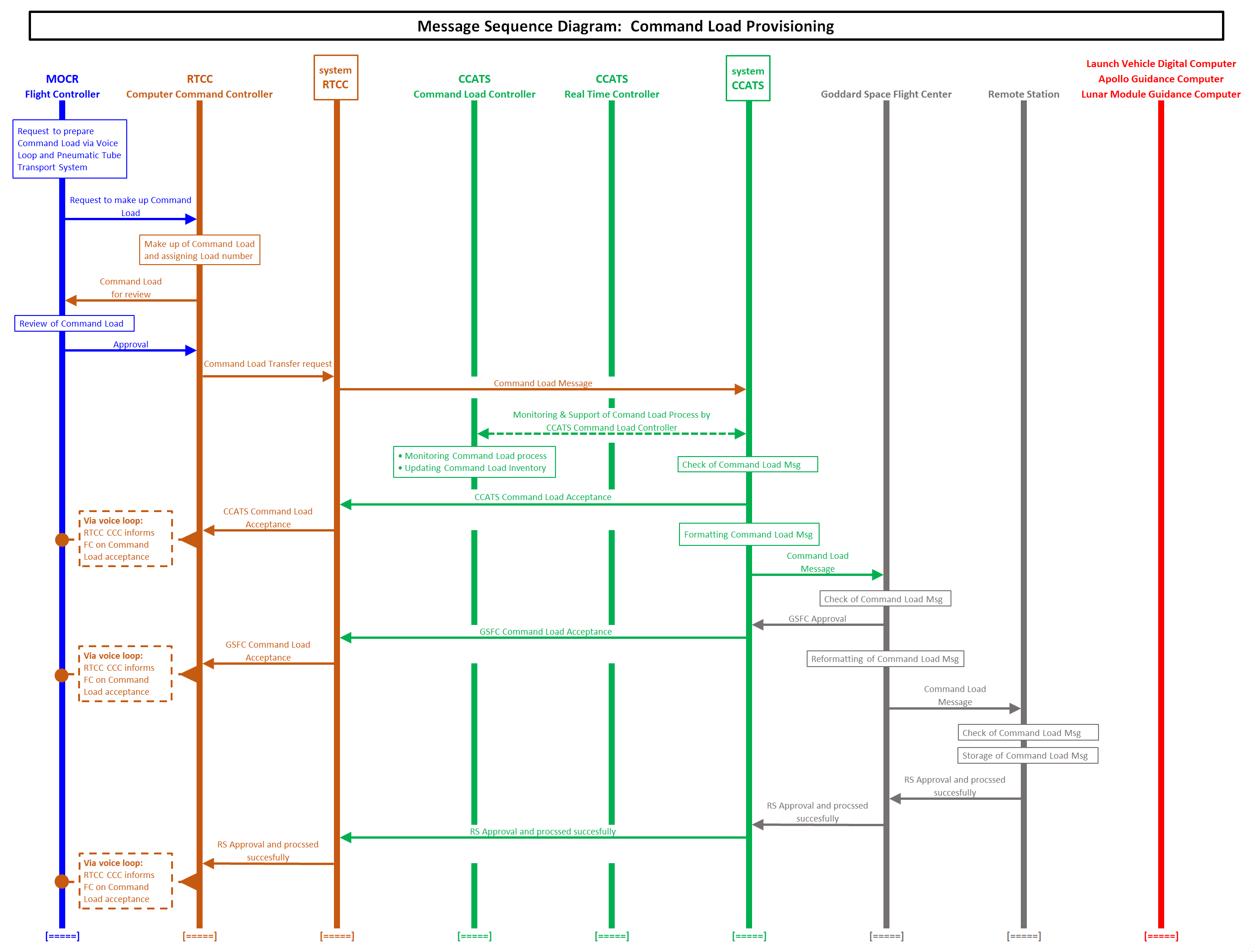
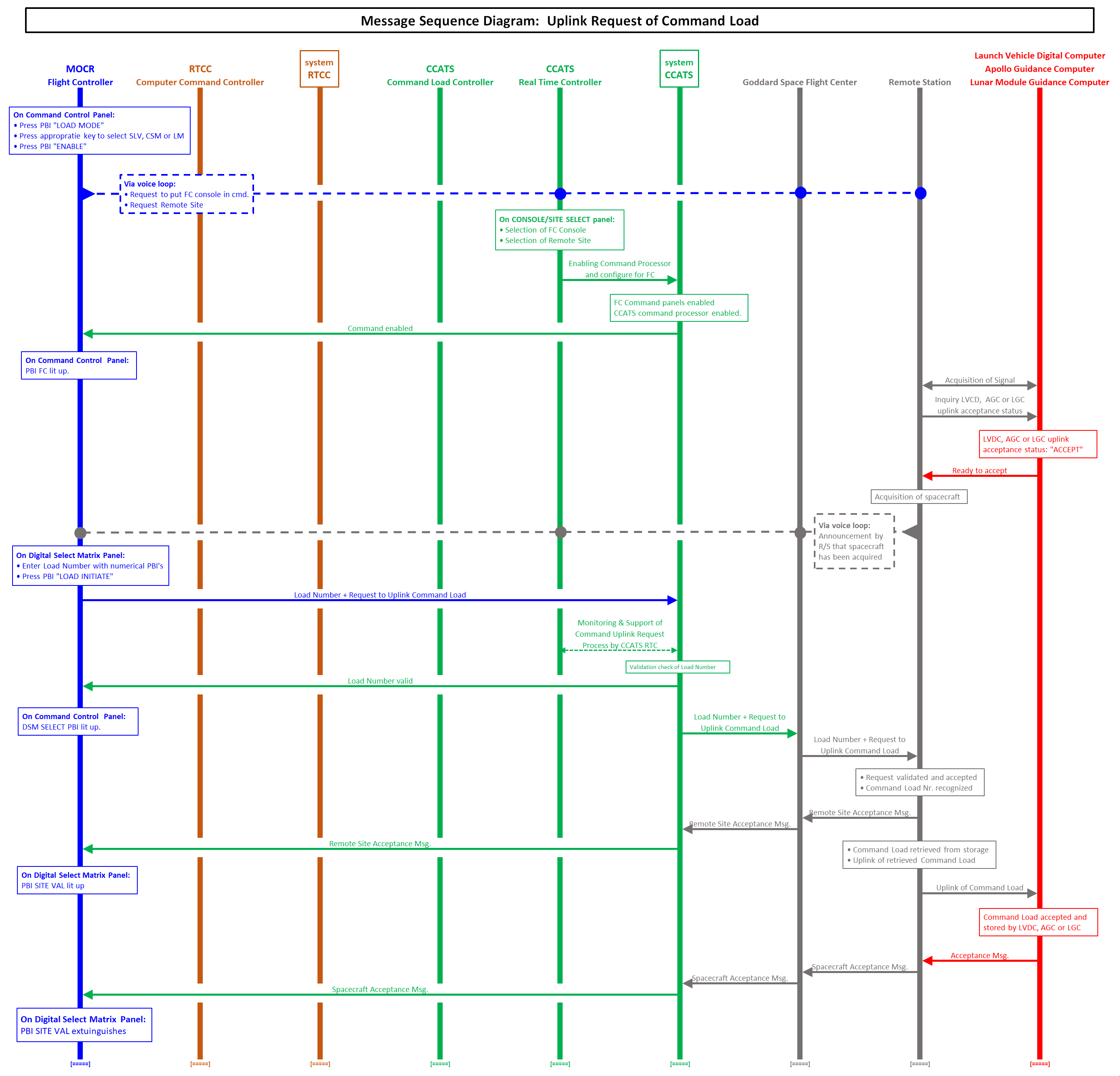
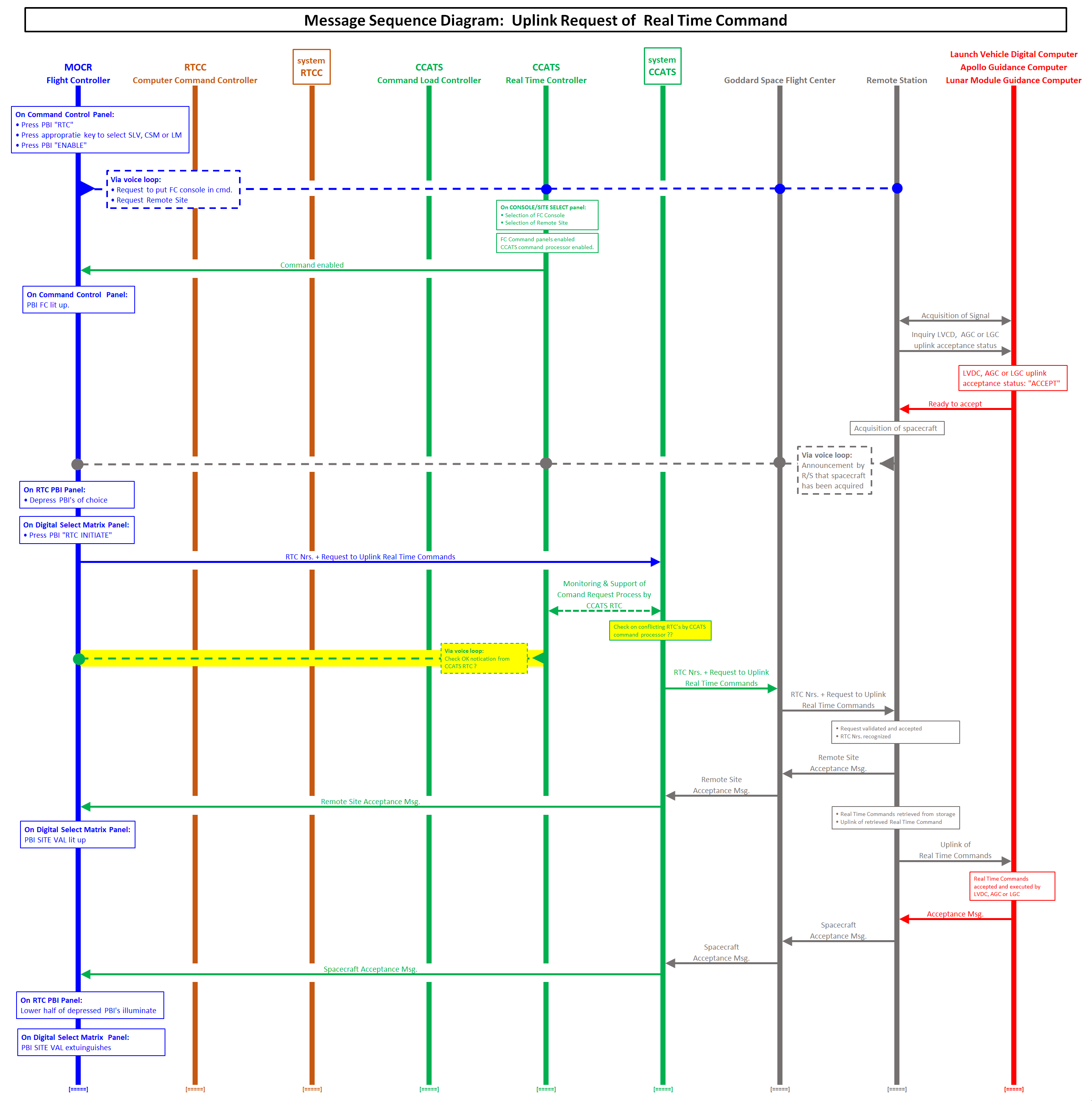
CCATS Communication Command And Telemetry System
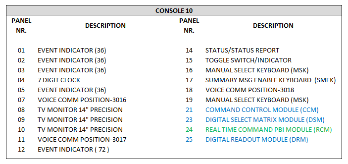
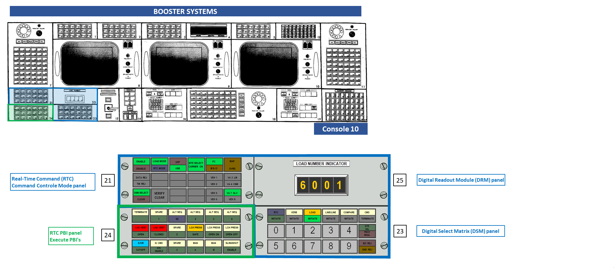
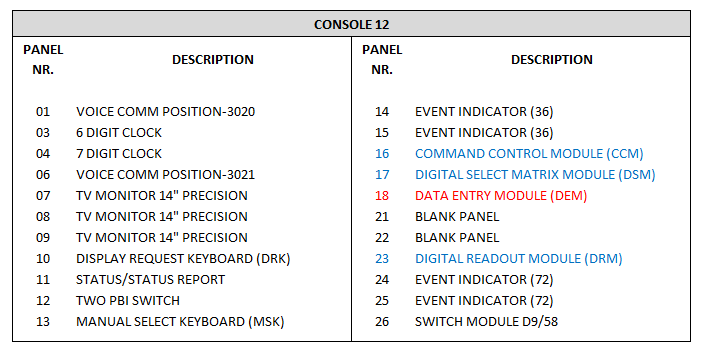
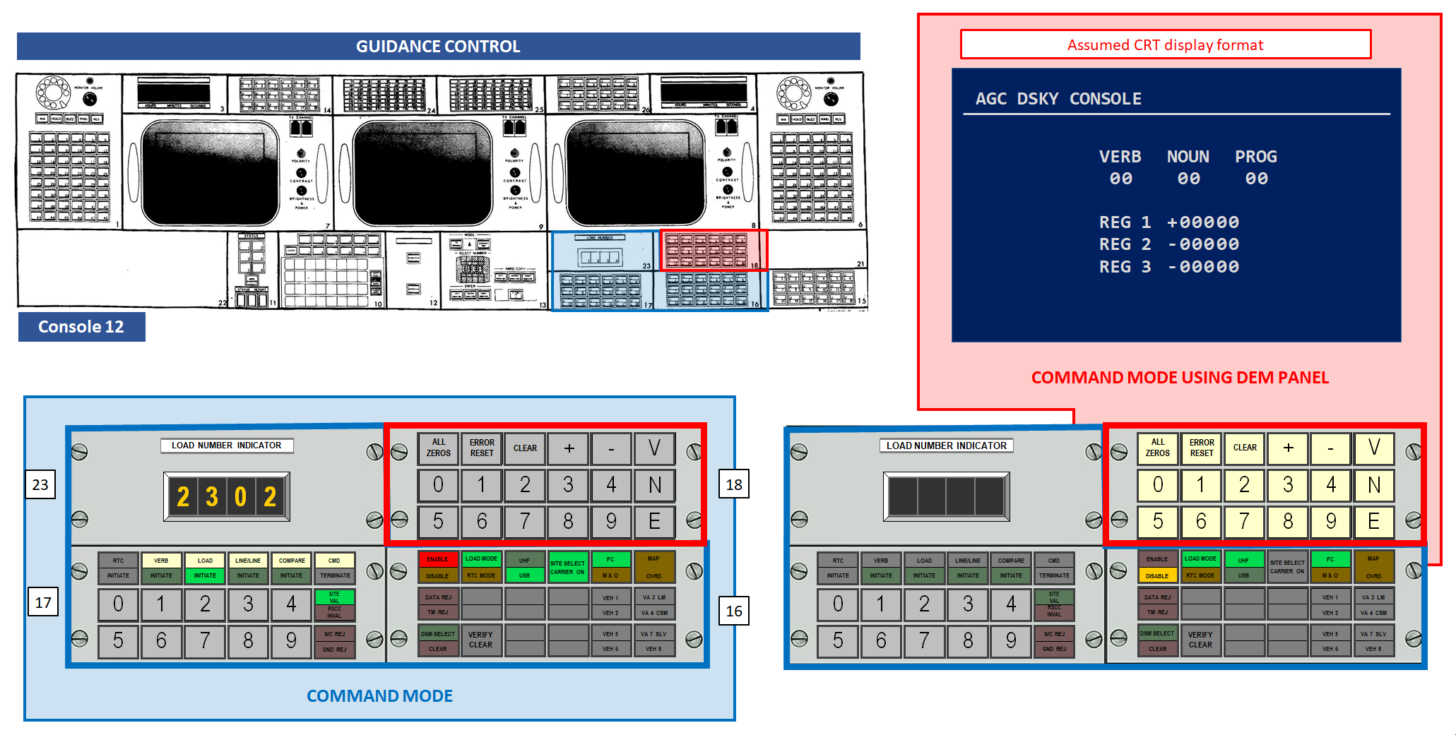
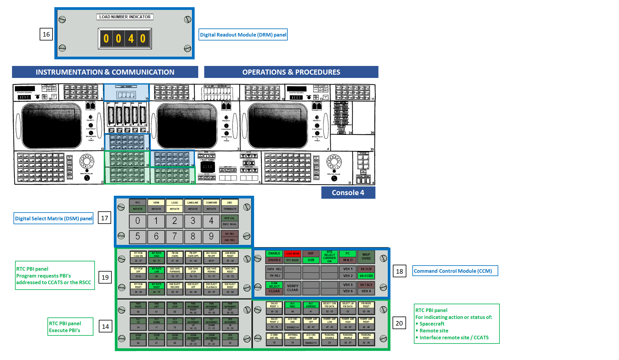
CCM Command Control Module
CIM Computer Input Multiplexer
CRP Computer Reset Pulse
DCS Digital Command System
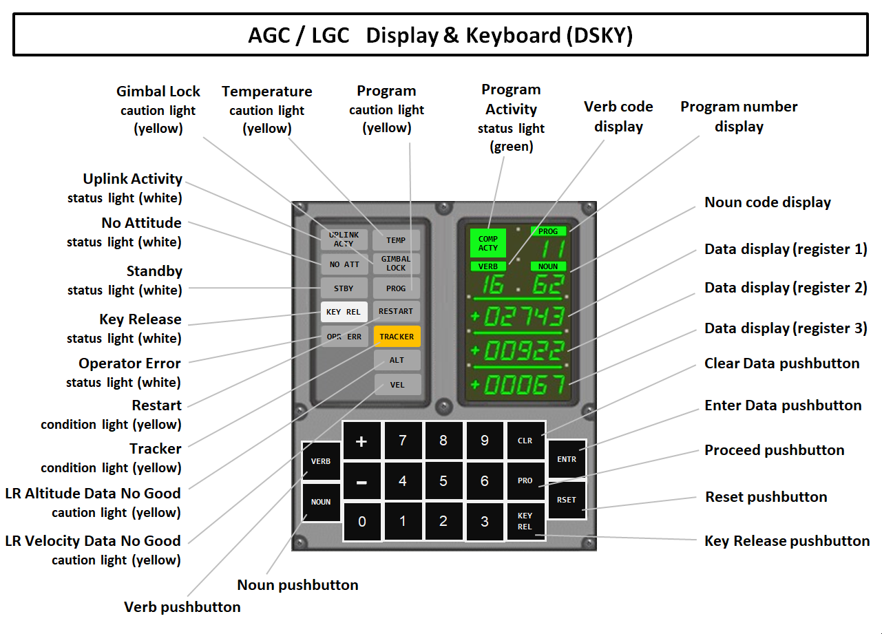
DSKY Display & Keyboard
DRM Digital Readout Module
DSM Digital Select Matrix Module
DSN Deep Space Network
GOSS Ground Operational Support System
GSFC Goddard Space Flight Center
GUIDO Guidance Officer
INCO Instrumentation and Communication Officer
JSC Johnson Space Center (Houston, Texas)
KSC Kennedy Space Center (Florida)
LGC Lunar Module Guidance Computer
LR Landing Radar
LVDC Launch Vehicle Digital Computer
MAP Message Acceptance Pulse
MCC Mission Control Center
MOCR Mission Operations Control Room
MSC Manned Spacecraft Center (Houston, Texas)
MSFN Manned Space Flight Network
PBI PushButton Indicator
RETRO Retrofire Officer
RSCC Remote Site Command Computer
RCM Real Time Command PBI Module
RTA Relative Time Accumulator
RTC Real-Time Command
RTCC Real-Time Computer Complex
TLM Telemetry
UHF Ultra High Frequency
USB Unified S-Band
Note: MSC has been renamed to JSC in 1973.

References
  1. Familiarization Manual
    Mission Control Center Houston
    PHO-FAM001, 30 June 1965
    by Western Development Laboratories, Houston Operations

  2. AS-508; MCC / MSFN; Mission Configuration / System Description
    March 1970
    by the Manned Spacecraft Center, Flight Support Division

  3. Mission Operational Configuration
    Mission J1, AS-510 / SC122 / LM10, Apollo 15
    PHO - TR155, 15 April 1971
    Manned Spacecraft Center, Houston

  4. Network Controller's Mission Report Apollo 11
    Prepared by Flight Support Division
    Manned Spacecraft Center, Houston
    15 August 1969

  5. Mission Operation Report
    Apollo 11 (AS-506) Mission
    Report No. M-932-69-11, 24 June 1969
    Prepared by Apollo Program Office
    Office of Manned Space Flight

  6. Apollo C-Band Radar Tracking Capability
    Apollo 11 (AS-506) Mission
    by P.R. Schmid
    Goddard Space Flight Center, Greenbelt, Maryland
    15 September 1967

  7. Ground Tracking of The Apollo
    Apollo 11 (AS-506) Mission
    by Friedrich O. Vonbun
    Goddard Space Flight Center, Greenbelt, Maryland
    1 January 1965

  8. Universal CSM Console Handbook
    S/C 106 and subsequent vehicles
    Section D5
    Flight Control Division
    Manned Spacecraft Center, Houston, May 1969
    Edited version of section D5
    (information still needs to be incorporated into this page)

  9. Introduction To Flight Control
    Handout, Revision A
    Flight Control Qualification Section
    Flight Control Division
    Manned Spacecraft Center, Houston, March 1968

  10. Apollo Digital Command System
    by C.B. Cox
    Goddard Space Flight Center, Greenbelt, Maryland
    Proceedings of the Apollo Unified S-Band Technical Conference
    July 14-15, 1965

  11. Apollo Command System - Ground Network Data Flow
    by J.E. Johnson
    Technical Memorandum 68-2034-8
    Bellcomm Inc.
    Washington DC, June 20, 1968


Site Map |  References |  Change History

Copyright 2023 by Sander Panhuyzen
Comments and questions welcome. All pictures and drawings contained on these pages are the author's, unless otherwise noted. No unauthorized reproduction without permission.