Concise description of the Apollo Launch Operations


Nourishing the Saturn V - Apollo stack

Figure 1.
The Saturn V moon rocket and its Launch Umbilical Tower (LUT) on launch pad 39A .

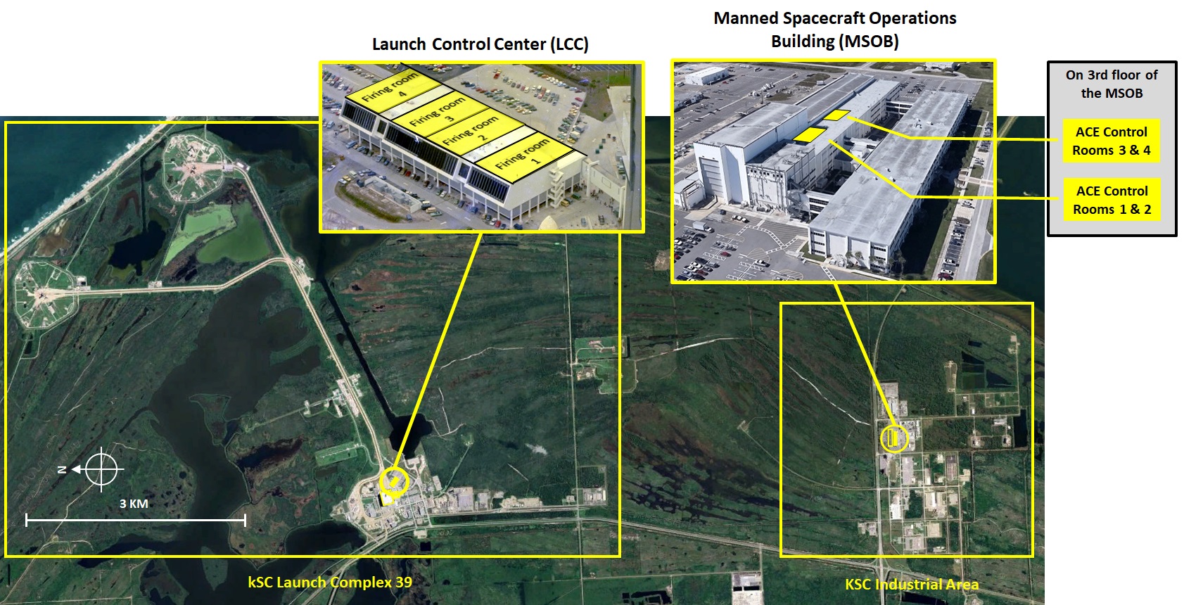
The whole rocket was a complex machine; the LUT and the two-storey-high grey launch platform contained a lot of equipment to monitor the numerous systems in the stack and to prepare the rocket for flight. Figure 2 is a functional system diagram in which it is shown how the Saturn V-Apollo stack was monitored from one of the three firing rooms in the LCC (Launch Control Centre) and from two control rooms in the MSOB (Manned Spacecraft Operations Building).

The first stage (S-IC stage) was running on kerosene and liquid oxygen. Both the second stage (S-II stage) and the third stage were running on liquid hydrogen and liquid oxygen.

The swing arms between the LUT and the launch vehicle were part of the Ground Support Equipment (GSE). The swing arms were used for propellant loading, all kinds of electrical connections, environmental control and vent lines for the fuel tanks filled with liquid hydrogen. The tail service masts and the swing arms nr. 4 through 8 were retracted at lift-off.

This hazardous gaseous hydrogen was burnt in special burn ponds at some distance from the launch pad. The tanks filled with liquid oxygen were vented through vent valves of the three stages in the open air to keep the tank pressure within limits.

The two-storey-high launch platform housed an impressive set of equipment to control the equipment of the launch umbilical tower. A computer system was part of that equipment, which also contained a so-called auto-sequencer, a computer program to control the countdown sequence during which hundreds of parameters of the launch vehicle and of the launch umbilical tower were checked and commands were sent to various systems according to a pre-determined sequence of which the "ignition" was the final command.

Photos: Credit to NASA. Scanning credit to Kipp Teague

KSC's Control and Monitoring Circuitry

Largely based on an enlarged version of ref.2 figure 2.5
Figure 2.
Diagram of the Global Functional Interconnection between the launch pad, the firing room and the spacecraft control rooms.

n this diagram is shown how the launch vehicle (Saturn V) and its ground support equipment were monitored and controlled from the firing room. Most of the ground support equipment was housed inside the launcher platform. The propellant storage tanks (for LOX, LH and RP-1) were located at the outer perimeter of the 1 square kilometer launch pad.

Spacecraft systems and systems of the Lunar Lander were in large part monitored from two control rooms in the Manned Spacecraft Operations Building (MSOB) located at the KSC Industrial Area about 6 km from the LCC.

Most consoles in the control rooms were used to control various systems remotely. But some consoles were interconnected with an RCA-110A computer system to initiate various test routines consisting of pre-programmed sequences of commands. The Saturn V had 7 groups of systems which were controlled remotely:

  1. The Apollo Command Module;
  2. the Apollo Service Module;
  3. the Lunar Module (ascent and descent stages);
  4. the Saturn V Instrument Unit;
  5. the S-IVB stage;
  6. the S-II stage and
  7. the S-IC stage.
With this elaborate complex of systems, thousands of parameters and event signals could be monitored and controlled. The Patch Distributor & Relay logic, the Digital Data Acquisition System and the RCA-110 computer were all located in the mobile launch platform. The onboard digital computers of the spacecrafts (CM AGC and LM AGC) and the launch vehicle (LVDC) were also tied into the command & control circuitry and enabled the controllers to configure these computers remotely.

The equipment designations A through F correspond to the designations in figure 3.


The control consoles in the LCC Firing Room

Floor plan based on ref.1 figure 8-16.
Figure 3.
Floor plan of the firing room.

The equipment designations A through F are corresponding to the equipment designations in figure 1.

On the floor plan it can be seen that for monitoring and managing the Saturn V launch vehicle, the managers and the engineers were located in separate areas. A similar arrangement has been set up for monitoring the spacecraft (Command Service Module and the Lunar Module). However, only the management was present in the firing room (area A); the engineers were located in Acceptance Checkout Equipment (ACE) Control Rooms. These rooms were part of the Manned Spacecraft Operations Building (MSOB) at the KSC industrial area some 7 km away. The floor plan of these ACE control rooms is shown in figure 4.


The control consoles in the ACE Control Rooms

Figure 4.
Floor plan of the Acceptance Checkout Equipment (ACE) Control Rooms.

ACE stands for Acceptance Checkout Equipment. The equipment has been designed for automated acceptance testing of Apollo spacecraft and enabled a team of testers to run through numerous test cycles on various systems of the spacecraft. A particular test run comprising various tests could be initiated by the press of a button. Test results were displayed analogously or digitally and were automatically stored on magnetic tape or recorded on chart recorders. When the spacecraft had passed the acceptance test, it was declared fit for mating with the Saturn launch vehicle in the Vertical Assembly Building (VAB).

There were two pairs of these control rooms; they were located on the third floor in the south wing of the Manned Spacecraft Operations Building (MSOB).
Each ACE Control Room was part of an ACE station. Such a station consisted of a control room, a computer room for processing data and commands from the control room and a terminal room to interface with the transmission system.
For more information about the ACE Control Rooms, click here.

The two pairs of these control stations allowed NASA to conduct testing at the KSC on two pairs of Apollo spacecraft (CSM + LM) simultaneously.
One pair of spacecraft could be located in the Vertical Assembly Building (VAB) for integration with the launch vehicle or at the launch pad for launch preparations. At the same time, testing in the MSOB on another pair of spacecraft for the next mission could be conducted because of this second pair of control stations.

When a pair of spacecraft (CSM + LM) was checked out and had been transported to the Vertical Assembly Building (VAB) to be mated with the Saturn V launch vehicle, it went through a sequence of prelaunch phases (see figure 5) from then on. With this sequence the highly complex Saturn V-Apollo stack was prepared for launch methodically to gradually bring it into a state of "ready for flight". During this process the stack went through a series of test cycles on various systems. During these test cycles systems began fulfilling their purpose for the first time, or systems began operating under different circumstances because of the constantly changing operational state of the stack. It was therefore paramount that the Apollo spacecrafts remained connected to the ACE control rooms for monitoring and testing when the stack was in the VAB or at the launch pad.


Locations of the Firing Rooms and the ACE Control Rooms

Courtesy of Google Earth
Figure 5.
Locations of the Firing Rooms and the ACE Control Rooms
During the launch phase the Saturn V with the Apollo spacecrafts (CSM + LM) on top was monitored from a firing room in the LCC building and from an ACE control room pair in the MSOB. The two facilities were about 7 km apart.
The LCC was part of Launch Complex 39, and the MSOB was located in the Industrial Area.

The Prelaunch Sequence
  illustrations, pictures, diagrams?
Based on ref.1 figure 8-19.
Figure 6.
The prelaunch sequence

A global overview of the prelaunch sequence. The assembly of the Saturn V with the spacecrafts on top was a delicate well choreographed process. The various tests on all the complicated systems were conducted in parallel with the assembly process.

The phases F, G and H were the pivotal phases leading up to the launch and were therefore rehearsed in a Count Down Demonstration Test (CDDT) to ascertain the launch readiness of the launch vehicle, spacecraft and ground support systems.


The final 4 hours of the prelaunch sequence

Based on ref.1 figure 1-8.
Figure 7.
The final 4 hours of the prelaunch sequence

In the final 3 minutes all checks were conducted by the "auto sequencer". At T-50 sec all systems of the Saturn V launch vehicle switched from external electrical power to internal (battery) power.


Acronyms
ACE Apollo Checkout Equipment
CD Count Down
CDDT Count Down Demonstration Test
CRT Cathode Ray Tube
CSM Command & Service Module
DDAS Digital Data Acquisition System
DEE Digital Event Evaluator
DTS Data Transmission System
IU Instrument Unit
LCC Launch Control Center
LH Liquid Hydrogen
LM Lunar Module
LOX Liquid Oxygen
LUT Launch Umbilical Tower
LVO Launch Vehicle Operations
MSOB Manned Spacecraft Operations Building
RP Rocket Propellant
SC Spacecraft
VAB Vertical Assembly Building

References
  1. Saturn V Flight Manual SA-503
    George C. Marshall Space Flight Center
    MSFC-MAN-503
    1 November 1968

  2. Countdown to a Moon Launch
    Preparing Apollo for Its Historic Journey
    by Jonathan Ward
    Springer, 2015


Site Map |  References |  Change History

Copyright 2021, 2023 by Sander Panhuyzen
Comments and questions welcome. All pictures and drawings contained on these pages are the author's, unless otherwise noted. No unauthorized reproduction without permission.