
Based on ref.1 photo HEAR No. FL-8-11-A-57
Hotspots:
Top green area is linked to Display Room description
Light red area is linked to Firing Room description
|
LCC cross section between gridlines (8) and (11)
The light-red section is depicting one of the four firing rooms. From right to left: the console area for the launch management team, for the engineering teams and the area with the instrument racks.
On the right side is an angled wall of large windows to provide a panoramic view of the launch site 5 km away. Fifteen large louvers were installed on the outside which could be quickly pivoted at their angled vertical center axis to form a protective wall against incoming debris in case of a catastrophic event on the launch pad.
|

|
|
Six 3 by 3 meter display screens kept the launch management team informed about the progress of the launch operations. The four display screens in the middle were used to display images from various video cameras located on the launch pad and on the launch umbilical tower and to display data. There were two display screens on either side of the four display screens mentioned above. The large display on the left side was used to display major launch events, and the display on the right side was used to show which tracking stations were receiving downlinked data from the launch vehicle.
Above the Firing Room a Display Room was situated containing four Eidophor projectors for displaying data and images from the various video cameras on four large projection screens.
|
|

Based on ref.1 photo HEAR No. FL-8-11-A-57
|
LCC cross section between gridlines (4) and (5)
|
|

Based on ref.1 photo HEAR No. FL-8-11-A-57 and ref.7 figure A-5
|
LCC Floor 1
|

Credit to Google Street View
|
|
Lobby and its main entrance.
|
|

Based on ref.1 photo HEAR No. FL-8-11-A-57 and ref.7 figure A-5
|
LCC Floor 2
|
|

Based on ref.1 photos HEAR No. FL-8-11-A-52 and HEAR No. FL-8-11-A-53
Complemented with information from ref.4 figure 8-16 and ref.2 figure 5-6.
|
Firing Room 4
Not equipped and never used for the Apollo missions.
It was used to display program evaluation and progress & planning charts during the construction of
Launch Complex 39 and the integration of Apollo/Saturn systems.
|
Firing Room 3
Apollo10
Skylab 2, 3 and 4
Apollo-Soyuz Test Project
|
Firing Room 2
Apollo 6, 9, 12, and 14
Saturn V Skylab 1 (OWS)
|
Firing Room 1
SA-500F
Apollo 4, 8, 11, 13, 15, 16, and 17
|
LCC Floor 3
The Launch Control Center has four large rooms for four firing rooms.
The rooms were corresponding to the four High Bay areas in the Vertical Assembly Building (VAB). This arrangement allowed for a simultaneous assembly and system testing of four launch vehicles. In the mid 1960s it was concluded that three High Bays and the corresponding three firing rooms were sufficient to meet the planned launch rate. The rooms which were used for the various missions are depicted above.
|
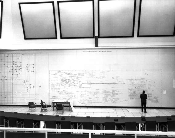
Firing Room 4 as management center
The drawing above depicts the temporary configuration of the Firing Room No.4 when it was used as the Site Activation Control Center (SACC).
Activation of Launch Complex 39 was a huge managerial challenge. Activation required the involvement of many contractor companies and the coordination of about 60 000 activities with many interdependencies.
Monitoring of progress was done at three management levels (A, B and C) to create a layered management visibility and layered management control. The highest level (level A) contained the Master Activation Schedule and was intended to provide visibility for top-level management. Level A and B information was presented on a large wall represented by the dark red line in the drawing. The three green lines in parallel are representing the walls on which level C information was presented.
Activation of Launch Complex 39 concerned the following five major elements:
- a hangar to assemble Saturn V rockets, each standing 110 meters tall;
- a mobile launch base on which the rockets will be assembled and from which they will be launched;
- a method of transporting rockets and launchers weighing 5450 metric Tons over a distance of 5.6 km to the launch site;
- a service structure that enables technicians to complete preparation of the Apollo spacecraft and the Saturn V stack at the launch site;
- a control center from which all these operations can be monitored and controlled.
The site activation itself included the following activities:
- construction;
- outfitting;
- installation;
- checkout of facilities and ground systems.
After the site activation, Firing Room 4 was used as a management center for launch operations to manage the numerous prelaunch activities for the Apollo missions.
|

From ref.2 figure 5-6
|
From ref.3 figure of chapter 15
|

From ref.2 figure 5-6
|
|
Display wall in the Site Activation Control Center for displaying level A and B management information.
|
The three display walls in the Site Activation Control Center for displaying level C management information.
|
|
|

Still from documentary film "Apollo 11"
|

Still from documentary film "Apollo 11"
|
|
Launch Operations Status Review Meeting in Firing Room 4
|
|

Based on ref.1 photos HEAR No. FL-8-11-A-54 and HEAR No. FL-8-11-A-55
Optical arrangement in the Display Rooms based on ref.5 page 78.
|
LCC Floor 4
This floor is comprised of conference rooms, office areas, and mechanical equipment rooms, among which are the large rooms in which the display equipment was located for the six large display screens in each firing room.
|

