|
Apollo CSM Navigation, Guidance and Control |
Content
|
| 1.Principles of operation |
 Based on ref.xxxx |
||
|
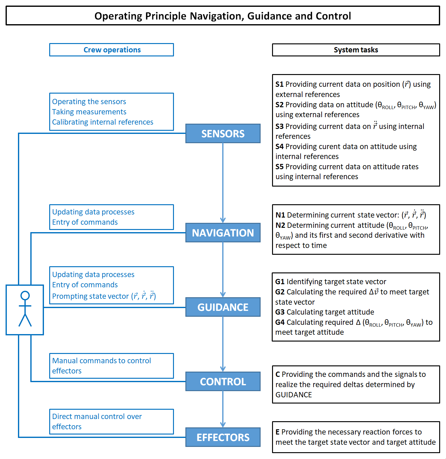
Figure 1.1 Operation principle of a Navigation, Guidance and Control System for controlling a flight trajectory of a spacecraft In this diagram are shown the five major building blocks for a system that controls the flightpath of a spacecraft. Each block represents a task:
|
||
 Based on ref.xxxx |
||
|
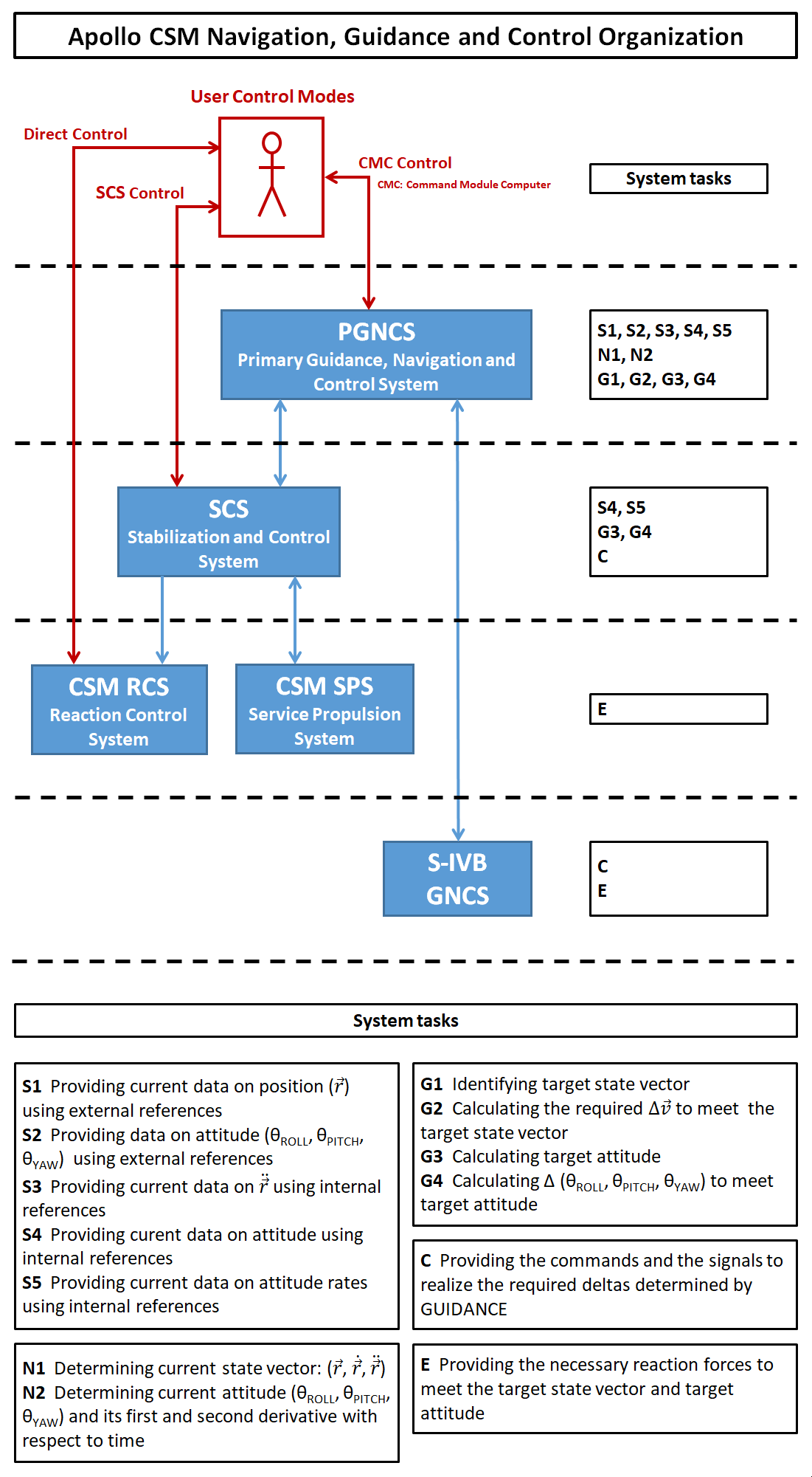
Figure 1.2 Global block diagram of the Apollo CSM Navigation, Guidance & Control System
In this diagram is shown how the principles of a NG&C system has been used in an Apollo CSM NG&C system. The PGNCS and the SCS each has its own sensor package. These packages are depicted in figure 3. As depicted in the diagram, user modes of control can be distinguished:
|
||
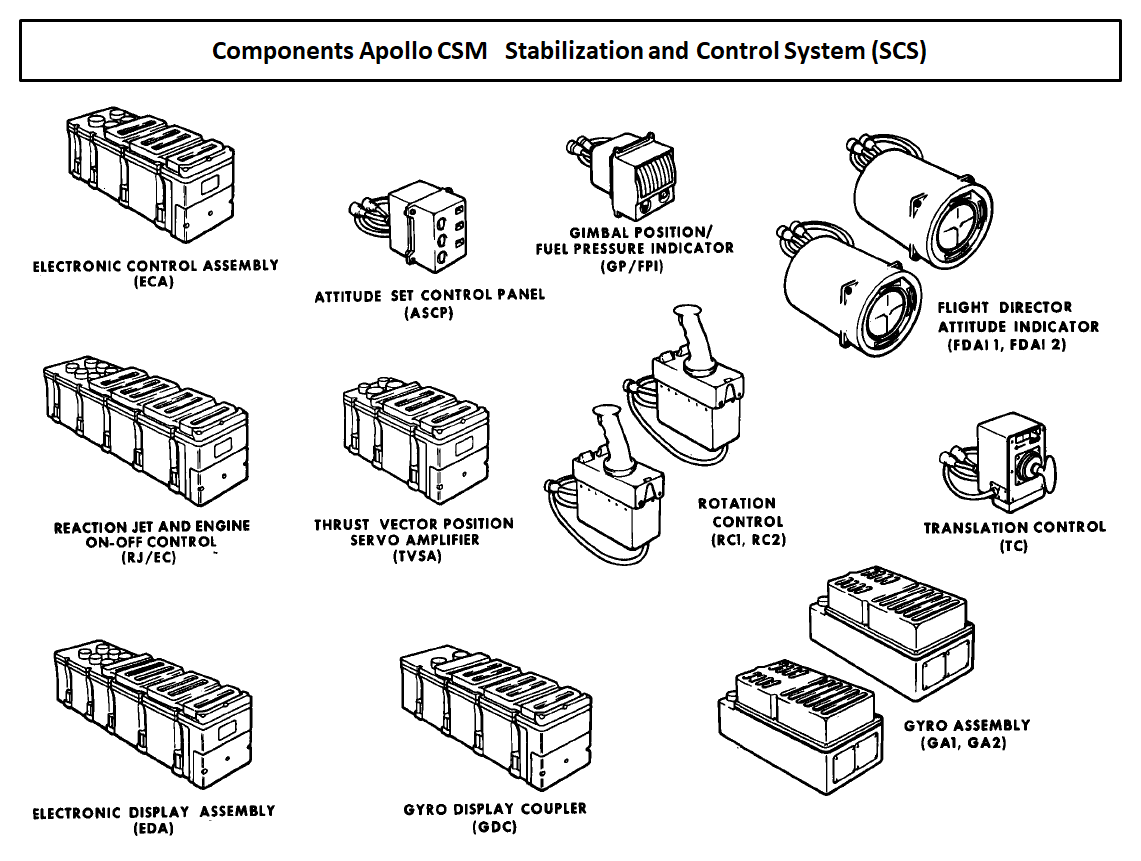
| 2.The hardware components of the CSM NGC System |
 Based on diagrams and description from various handbooks and technical notes. (References still need to be mentioned.) |
|
|
Figure 2.1 Detailed systems diagram of the Apollo CSM Navigation, Guidance and Control System |
|
|
TOPICS TO BE ADDRESSED
Some remarks about the SCS control mode
Flight Director Attitude Indicator (FDAI)
GNC contigency during the boost phase |
Navigation sources The Command Module Computer (CMC) of the Apollo spacecraft can be considered has the heart of the GNC system. In order for the CMC to know the position and attitude in space it relied on various information souces:
Modes of operation
Alignment procedures for the IMU and the GDC
Trajectory control
Attitude control |
| Text for layout testing purposes. Text for layout testing purposes. Text for layout testing purposes. Text for layout testing purposes. Text for layout testing purposes. Text for layout testing purposes. | Text for layout testing purposes. Text for layout testing purposes. Text for layout testing purposes. Text for layout testing purposes. Text for layout testing purposes. Text for layout testing purposes. |
 Based on ref.xxxx |
|
|
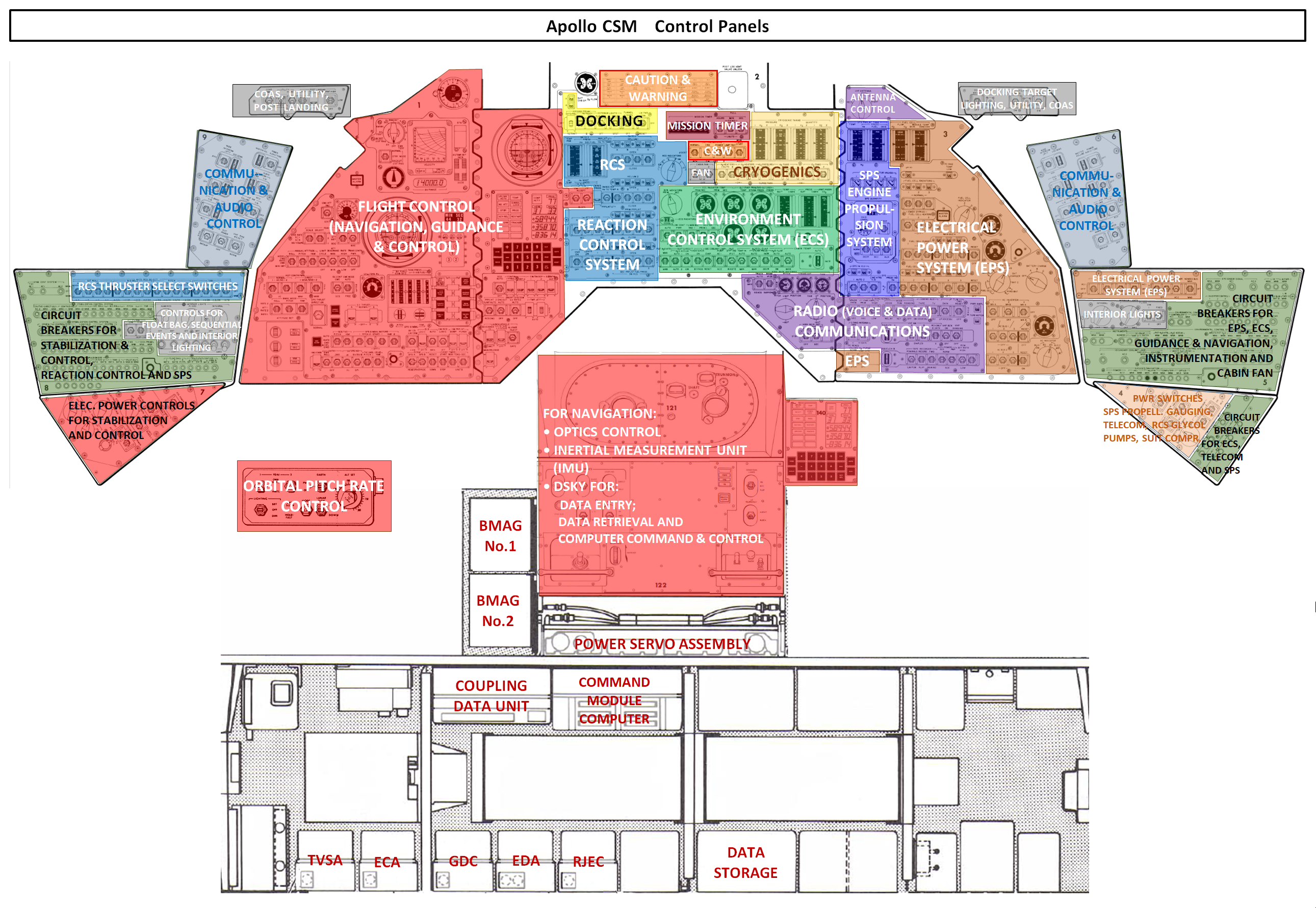
Figure 2.2 The Apollo CSM control panel and the systems in the lower equipment bay |
|
Text
|
|
| Text for layout testing purposes. Text for layout testing purposes. Text for layout testing purposes. Text for layout testing purposes. Text for layout testing purposes. Text for layout testing purposes. | Text for layout testing purposes. Text for layout testing purposes. Text for layout testing purposes. Text for layout testing purposes. Text for layout testing purposes. Text for layout testing purposes. |
 Based on ref.xxxx |
|
|
Figure 2.3 Text |
|
|
Text Text for layout testing purposes. Text for layout testing purposes. Text for layout testing purposes. Text for layout testing purposes. Text for layout testing purposes. Text for layout testing purposes. |
Text Text for layout testing purposes. Text for layout testing purposes. Text for layout testing purposes. Text for layout testing purposes. Text for layout testing purposes. Text for layout testing purposes. Text for layout testing purposes. Text for layout testing purposes. Text for layout testing purposes. Text for layout testing purposes. Text for layout testing purposes. Text for layout testing purposes. |
| Text for layout testing purposes. Text for layout testing purposes. Text for layout testing purposes. Text for layout testing purposes. Text for layout testing purposes. Text for layout testing purposes. | Text for layout testing purposes. Text for layout testing purposes. Text for layout testing purposes. Text for layout testing purposes. Text for layout testing purposes. Text for layout testing purposes. |
|
|||||||||||||||||||||
|
Figure 2.4 Apollo CSM control panels for operating the Primary Guidance, Navigation & Control System and the Stabilization & Control System |
|||||||||||||||||||||
|
Eight groups of switches for selecting the NGC control modes. In the picture above seven groups of switches are indicated which were used to select the various control modes for attitude & translation control and thrust vector control.
|
|
||||||||||||||||||||

| Text for layout testing purposes. Text for layout testing purposes. Text for layout testing purposes. Text for layout testing purposes. Text for layout testing purposes. Text for layout testing purposes. |
 Credit to NASA |
|
Figure 2.5
Text |
 Credit to NASA |
|
Figure 2.6 Text for layout testing purposes. Text for layout testing purposes. Text for layout testing purposes. Text for layout testing purposes. Text for layout testing purposes. Text for layout testing purposes. Text for layout testing purposes. |

Diagram based on xxxxxxx |
|
| Figure 2.7 | |
|
Text for layout testing purposes.
Text for layout testing purposes. Text for layout testing purposes. Text for layout testing purposes. Text for layout testing purposes. Text for layout testing purposes. Text for layout testing purposes. Text for layout testing purposes. Text for layout testing purposes. Text for layout testing purposes. Text for layout testing purposes. Text for layout testing purposes. Text for layout testing purposes. |
|
| 3.Attitude & Translation Control Modes |
|
||||||||||||||||||||||||||||||||||||||||||||||||||||||||||||||||||||||||||||||||||||||||||||||||||||||||||||||||||||||||||||||||||||||||||||||||||||||||||||||||||||||||||||||||||||||||||||||||||||||||||||||||||||||||||||||||||||||||||||||||||||||||||||||||||||||||||||||||||||||||||||||||||||||||||||||||||||||||||||||||||
|
MANUAL ATTITUDE and BMAG could each operate in three modes. For each rotational movement, YAW, PITCH and ROLL, these control modes could be selected separately. For example, for YAW and PITCH MANUAL ATTITUDE control mode, ACCEL CMD could be selected and for ROLL, the control mode RATE CMD. Figures 3.1 through 3.7 show the signal paths between the subsystems that were relevant in the various control modes. |
"not relevant" means that the switch positions does not affect the concerned control mode. | |||||||||||||||||||||||||||||||||||||||||||||||||||||||||||||||||||||||||||||||||||||||||||||||||||||||||||||||||||||||||||||||||||||||||||||||||||||||||||||||||||||||||||||||||||||||||||||||||||||||||||||||||||||||||||||||||||||||||||||||||||||||||||||||||||||||||||||||||||||||||||||||||||||||||||||||||||||||||||||||||
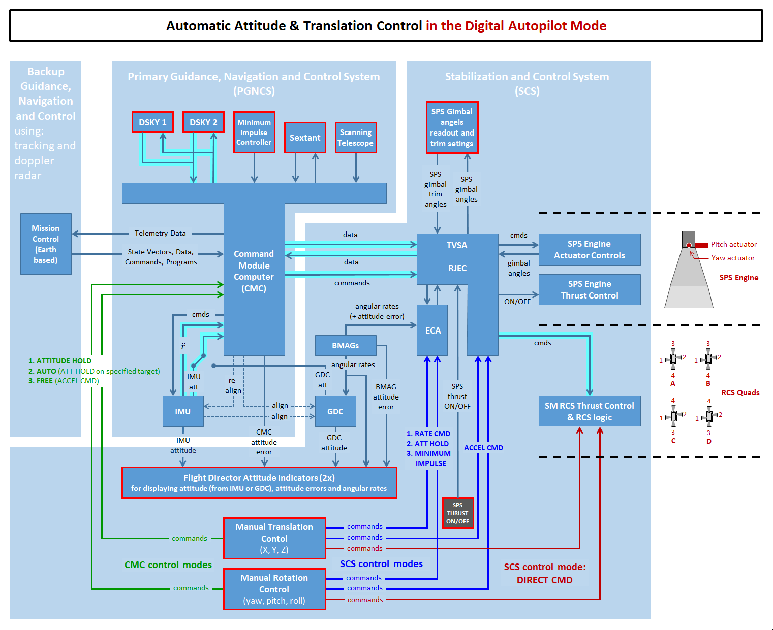
Diagram based on xxxxxxx |
|
| Figure 3.1 | |
|
Text for layout testing purposes.
Text for layout testing purposes. Text for layout testing purposes. Text for layout testing purposes. Text for layout testing purposes. Text for layout testing purposes. Text for layout testing purposes. Text for layout testing purposes. Text for layout testing purposes. Text for layout testing purposes. Text for layout testing purposes. Text for layout testing purposes. Text for layout testing purposes. |
|

Diagram based on xxxxxxx |
|
| Figure 3.2 | |
|
Text for layout testing purposes.
Text for layout testing purposes. Text for layout testing purposes. Text for layout testing purposes. Text for layout testing purposes. Text for layout testing purposes. Text for layout testing purposes. Text for layout testing purposes. Text for layout testing purposes. Text for layout testing purposes. Text for layout testing purposes. Text for layout testing purposes. Text for layout testing purposes. |
|

Diagram based on xxxxxxx |
|
| Figure 3.3 | |
|
Text for layout testing purposes.
Text for layout testing purposes. Text for layout testing purposes. Text for layout testing purposes. Text for layout testing purposes. Text for layout testing purposes. Text for layout testing purposes. Text for layout testing purposes. Text for layout testing purposes. Text for layout testing purposes. Text for layout testing purposes. Text for layout testing purposes. Text for layout testing purposes. |
|

Diagram based on xxxxxxx |
|
| Figure 3.4 | |
|
Text for layout testing purposes.
Text for layout testing purposes. Text for layout testing purposes. Text for layout testing purposes. Text for layout testing purposes. Text for layout testing purposes. Text for layout testing purposes. Text for layout testing purposes. Text for layout testing purposes. Text for layout testing purposes. Text for layout testing purposes. Text for layout testing purposes. Text for layout testing purposes. |
|
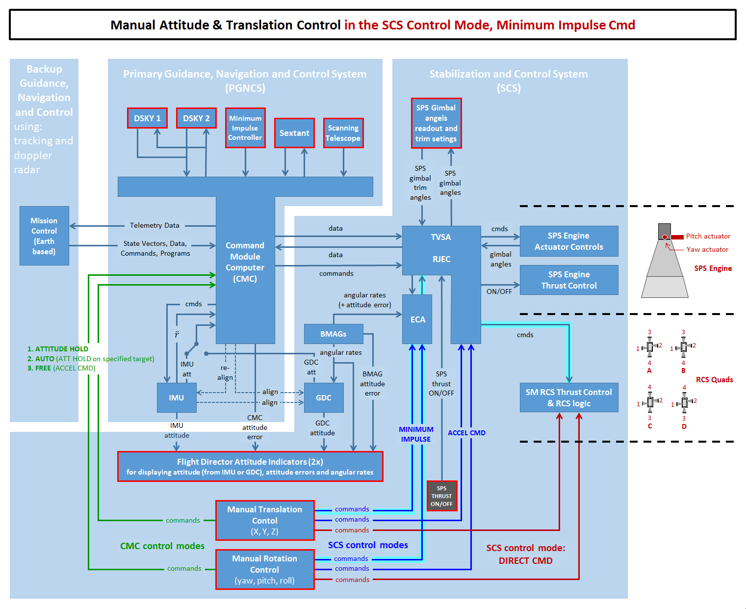
Diagram based on xxxxxxx |
|
| Figure 3.5 | |
|
Text for layout testing purposes.
Text for layout testing purposes. Text for layout testing purposes. Text for layout testing purposes. Text for layout testing purposes. Text for layout testing purposes. Text for layout testing purposes. Text for layout testing purposes. Text for layout testing purposes. Text for layout testing purposes. Text for layout testing purposes. Text for layout testing purposes. Text for layout testing purposes. |
|

Diagram based on xxxxxxx |
|
| Figure 3.6 | |
|
Text for layout testing purposes.
Text for layout testing purposes. Text for layout testing purposes. Text for layout testing purposes. Text for layout testing purposes. Text for layout testing purposes. Text for layout testing purposes. Text for layout testing purposes. Text for layout testing purposes. Text for layout testing purposes. Text for layout testing purposes. Text for layout testing purposes. Text for layout testing purposes. |
|

Diagram based on xxxxxxx |
|
| Figure 3.7 | |
|
Text for layout testing purposes.
Text for layout testing purposes. Text for layout testing purposes. Text for layout testing purposes. Text for layout testing purposes. Text for layout testing purposes. Text for layout testing purposes. Text for layout testing purposes. Text for layout testing purposes. Text for layout testing purposes. Text for layout testing purposes. Text for layout testing purposes. Text for layout testing purposes. |
|
| 4.Thrust Vector Control Modes |
|
||||||||||||||||||||||||||||||||||||||||||||||||||||||||||||||||||||||||||||||||||||||||||||||||||||||||||||||||||||||||||||||||||||||||||||||
| "not relevant" means that the switch positions does not affect the concerned control mode. | ||||||||||||||||||||||||||||||||||||||||||||||||||||||||||||||||||||||||||||||||||||||||||||||||||||||||||||||||||||||||||||||||||||||||||||||

Diagram based on xxxxxxx |
|
| Figure 4.1 | |
|
Text for layout testing purposes.
Text for layout testing purposes. Text for layout testing purposes. Text for layout testing purposes. Text for layout testing purposes. Text for layout testing purposes. Text for layout testing purposes. Text for layout testing purposes. Text for layout testing purposes. Text for layout testing purposes. Text for layout testing purposes. Text for layout testing purposes. Text for layout testing purposes. |
|

Diagram based on xxxxxxx |
|
| Figure 4.2 | |
|
Text for layout testing purposes.
Text for layout testing purposes. Text for layout testing purposes. Text for layout testing purposes. Text for layout testing purposes. Text for layout testing purposes. Text for layout testing purposes. Text for layout testing purposes. Text for layout testing purposes. Text for layout testing purposes. Text for layout testing purposes. Text for layout testing purposes. Text for layout testing purposes. |
|

Diagram based on xxxxxxx |
|
| Figure 4.3 (to be checked) | |
|
Text for layout testing purposes.
Text for layout testing purposes. Text for layout testing purposes. Text for layout testing purposes. Text for layout testing purposes. Text for layout testing purposes. Text for layout testing purposes. Text for layout testing purposes. Text for layout testing purposes. Text for layout testing purposes. Text for layout testing purposes. Text for layout testing purposes. Text for layout testing purposes. |
|

Diagram based on xxxxxxx |
|
| Figure 4.4 | |
|
Text for layout testing purposes.
Text for layout testing purposes. Text for layout testing purposes. Text for layout testing purposes. Text for layout testing purposes. Text for layout testing purposes. Text for layout testing purposes. Text for layout testing purposes. Text for layout testing purposes. Text for layout testing purposes. Text for layout testing purposes. Text for layout testing purposes. Text for layout testing purposes. |
|

Diagram based on xxxxxxx |
|
| Figure 4.5 | |
|
Text for layout testing purposes.
Text for layout testing purposes. Text for layout testing purposes. Text for layout testing purposes. Text for layout testing purposes. Text for layout testing purposes. Text for layout testing purposes. Text for layout testing purposes. Text for layout testing purposes. Text for layout testing purposes. Text for layout testing purposes. Text for layout testing purposes. Text for layout testing purposes. |
|
| 5.Title |
| Acronyms | |
|---|---|
|
ASCP Attitude Set Control Panel
BMAG Body Mounted Attitude Gyro CDU Coupling Data Unit CMC Command Module Computer DSKY Display and Keyboard ECA Electronic Control Assembly EDA Electronic Display Assembly FDAI Flight Director Attitude Indicator FPI Fuel Pressure Indicator GDC Gyro Display Coupler GPI Gimbal Position Indicator IMU Inertial Measurement Unit MIC Minimum Impulse Controller MTVC Manual Thrust Vector Control |
ORDEAL Orbital Rate Display - Earth And Lunar
PIPA Pulse Integrating Pendulous Accelerometer PGNCS Primary Guidance Navigation & Control System RCS Reaction Control System RHC Rotation Hand Controller RJEC Reaction Jet & Engine Control SCS Stabilization and Control System SPS Service Propulsion System THC Translation Hand Controller TVC Thrust Vector Control TVSA Thrust Vector Servo Amplifier UPTLM Uplink Telemetry |
References
|
Site Map |
References |
Change History
|
Comments and questions are welcome. All pictures and drawings contained on and through these pages are the author's, unless otherwise noted. No unauthorized reproduction without permission. |